Milling cutter of son and mother blade structure

A kind of technology of milling cutter and mother-in-law, which is applied in the field of milling cutters with auxiliary cutting sipes with spiral straps. It can solve the problems of insufficient rigidity, uneven cutting edge resistance, and reduced processing surface quality, so as to improve the performance of shock resistance and wear resistance. Effect of reducing cutting resistance and improving machining efficiency

Inactive Publication Date: 2017-09-08
江苏科比特科技有限公司
View PDF6 Cites 0 Cited by
  • Summary
  • Abstract
  • Description
  • Claims
  • Application Information

AI Technical Summary

Problems solved by technology

[0003] As we all know, on the traditional end mill, there are three or four counterclockwise helical milling grooves on the cylindrical surface, and the groove depths are all equal in depth, such as Figure 1-2 As shown, the overall rigidity of the cutter body is insufficient, the resistance of the cutting edge cannot be dispersed, and the chip breaking function is not very good. Under the conditions of high-speed and high-feed cutting, the cutter is prone to vibration, resulting in a decrease in the quality of the processed surface and scrapping the product. , causing damage to the machine tool in severe cases
Moreover, in the metal cutting field of slot milling, end milling, and cavity milling, the selection of cutting tools is different, and different milling cutters need to be selected according to different workpiece conditions. The existing cutting tools cannot be used for multiple cutting tools. The form of cutting processing increases the purchase of tool types and increases the cost of purchase and management
Therefore, it is necessary to improve the structure of the milling cutter to solve the defects of insufficient overall rigidity of the cutter body in the design and manufacture of the traditional end mill, the resistance of the cutting edge is not scattered, and the chip breaking function is not good.

Method used


Image

  • Milling cutter of son and mother blade structure
  • Milling cutter of son and mother blade structure
  • Milling cutter of son and mother blade structure

Examples


Embodiment 1

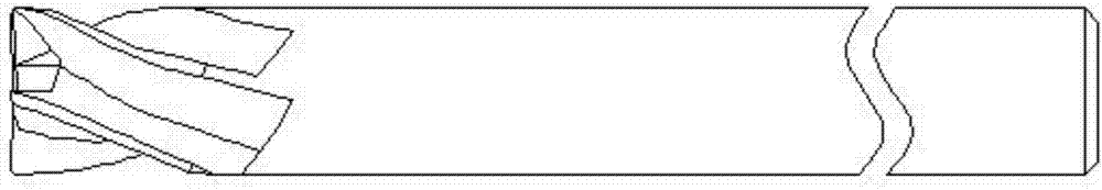
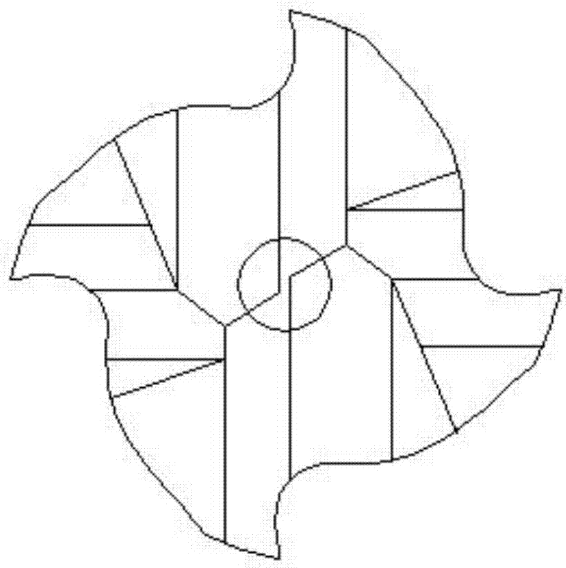
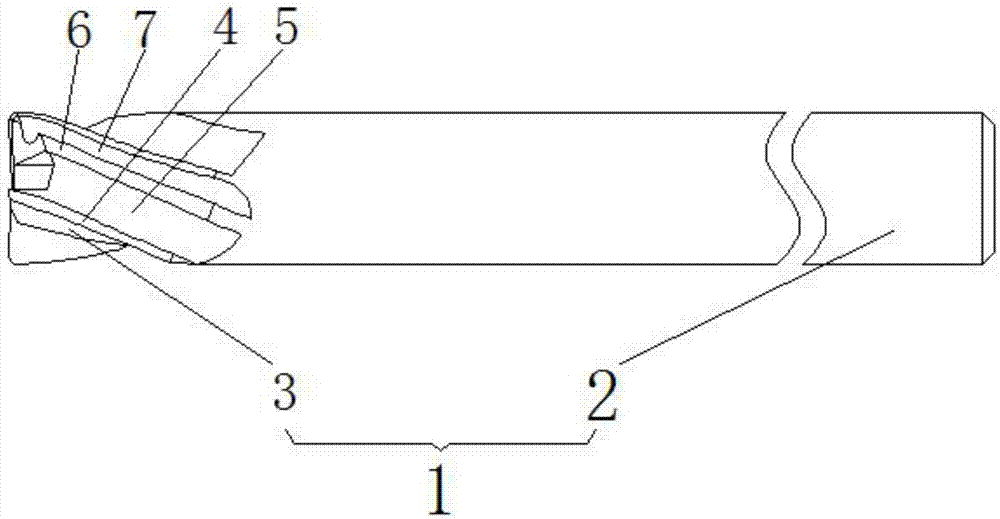
[0019] Embodiment 1: A milling cutter with a sub-female blade structure of the present invention includes a cutter body 1, and the cutter body includes a cutter base 2 arranged at the tail end of the cutter body 1 and a cutter head 3 arranged at the front end; The cutter head 3 is provided with four main cutting edges 4 that are uniformly distributed in a counterclockwise helical shape, and the clockwise front side of each main cutting edge 4 is provided with a main cutting groove 5; Minor cutting edges 6 are provided on the clockwise rear sides of the cutting edges 4 , and minor cutting grooves 7 are formed between the adjacent major cutting edges 4 and minor cutting edges 6 . The included angle between each major cutting edge 4 and the minor cutting edge 6 located at the rear side in the clockwise direction is 30°; the end of the minor cutting edge 6 is lower than the end of the major cutting edge 4 .

Embodiment 2

[0020] Embodiment 2: A milling cutter with a sub-matrix blade structure of the present invention includes a cutter body 1, and the cutter body includes a cutter base 2 arranged at the tail end of the cutter body 1 and a cutter head 3 arranged at the front end; The cutter head 3 is provided with four main cutting edges 4 that are uniformly distributed in a counterclockwise helical shape, and the clockwise front side of each main cutting edge 4 is provided with a main cutting groove 5; Minor cutting edges 6 are provided on the clockwise rear sides of the cutting edges 4 , and minor cutting grooves 7 are formed between the adjacent major cutting edges 4 and minor cutting edges 6 . The included angle between each major cutting edge 4 and the minor cutting edge 6 located at the rear side in the clockwise direction is 30°; the ends of the minor cutting edges 6 are flush with the ends of the major cutting edges 4 .

Embodiment 3

[0021] Embodiment 3: A milling cutter with a sub-matrix blade structure of the present invention includes a cutter body 1, and the cutter body includes a cutter base 2 arranged at the tail end of the cutter body 1 and a cutter head 3 arranged at the front end; The cutter head 3 is provided with four main cutting edges 4 that are uniformly distributed in a counterclockwise helical shape, and the clockwise front side of each main cutting edge 4 is provided with a main cutting groove 5; Minor cutting edges 6 are provided on the clockwise rear sides of the cutting edges 4 , and minor cutting grooves 7 are formed between the adjacent major cutting edges 4 and minor cutting edges 6 . The included angle between each major cutting edge 4 and the minor cutting edge 6 located at the rear side in the clockwise direction is 35°; the end of the minor cutting edge 6 is lower than the end of the major cutting edge 4 .


PUM


Abstract

The invention discloses a milling cutter of a son and mother blade structure. The milling cutter comprises a cutter body. The cutter body comprises a cutter base arranged on the tail end portion of the cutter body and a cutter head arranged on the front end portion. The cutter head is provided with a plurality of main cutting blades which are evenly distributed in an anticlockwise spiral line shape, the clockwise front side of each main cutting blade is provided with a main cutting groove, the clockwise rear side of each main cutting blade is provided with an auxiliary cutting blade, and an auxiliary cutting groove is formed between the adjacent main cutting blade and auxiliary cutting blade. The milling cutter solves the problems that according to a traditional vertical milling cutter, the integral rigidity of a manufactured cutter body is insufficient, the resistance of cutting blades cannot be dispersed, the chip breaking function is not good, and rough machining and finish machining cannot be integrated.

Description

technical field [0001] The invention relates to the technical field of milling cutters, in particular to a milling cutter with a helical strap and auxiliary cutting sipes suitable for milling such as slot milling, end milling, and cavity milling. Background technique [0002] With the maturity of computer numerical control (CNC) processing technology, more and more attention is paid to processing efficiency, which directly determines the processing cost and the length of delivery cycle. In view of this situation, there is an urgent need to improve The processing efficiency of traditional tools and the improvement of tool life ensure the stability of the cutting process during machining, and the suppression of frequent tool changes during machining plays a great role in improving the efficiency of machining. [0003] As we all know, on the traditional end mill, there are three or four counterclockwise helical milling grooves on the cylindrical surface, and the groove depths a...

Claims


Application Information

Patent Timeline
Patent Type & Authority Applications(China)
IPC IPC(8): B23C5/02
CPCB23C5/02B23C2210/54
Inventor 姚军谢明许九月李东
Owner 江苏科比特科技有限公司
Why Eureka
Try Eureka