
Continuous die bonding device and die bonding method of light emitting diode (LED)

A technology of LED chips and solid crystals, which is applied in semiconductor/solid-state device manufacturing, electrical components, circuits, etc., and can solve problems that have not been seen involving continuous SiC free thin-film ceramic heat-dissipating substrates

Inactive Publication Date: 2017-09-08
XIAMEN UNIV
View PDF10 Cites 21 Cited by
  • Summary
  • Abstract
  • Description
  • Claims
  • Application Information

AI Technical Summary

Problems solved by technology

[0007] Chinese patent CN106024647A discloses a low-cost production process of COB packaged devices. The existing support is replaced by the PCB board patterning process, which saves the cost of mold opening and improves efficiency and flexibility. However, it is only suitable for large plates of metal or Ceramic substrate
[0011] At present, there is no LED die-bonding device or die-bonding method involving continuous SiC free thin-film ceramic heat dissipation substrates in China.

Method used


Image

  • Continuous die bonding device and die bonding method of light emitting diode (LED)
  • Continuous die bonding device and die bonding method of light emitting diode (LED)
  • Continuous die bonding device and die bonding method of light emitting diode (LED)

Examples


Embodiment Construction

[0068] In order to make the purpose, technical solutions and advantages of the present invention more clear and understandable, the present invention will be described below in conjunction with exemplary embodiments and with reference to the accompanying drawings.

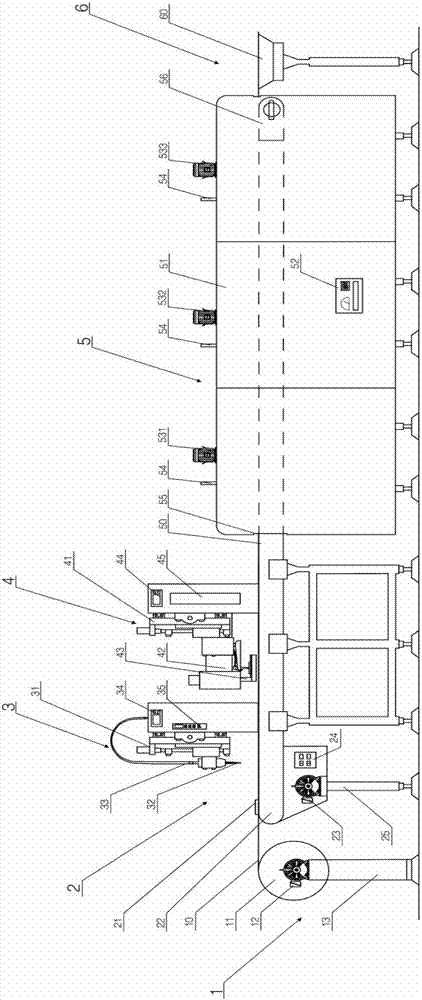
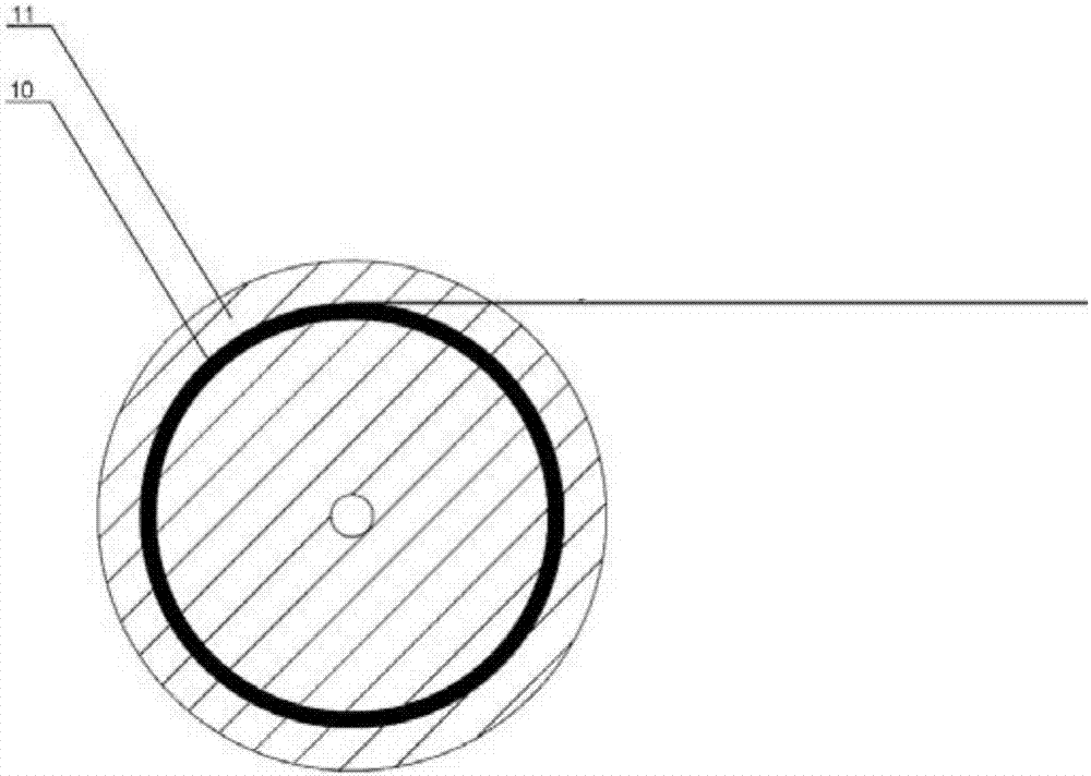
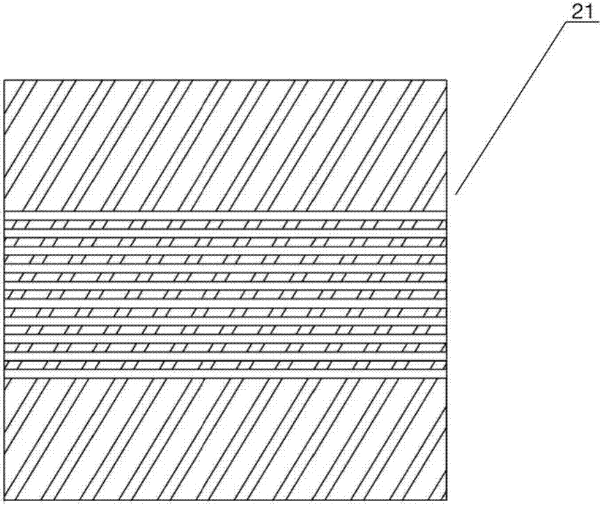
[0069] This kind of LED continuous crystal bonding device provided by the present invention, such as figure 1 As shown, it includes: a substrate film delivery system 1 , a transmission system 2 , a dispensing system 3 , a crystal bonding system 4 , a heating system 5 and a substrate film delivery system 6 . The substrate film-out system 1 includes a silicon carbide thin film substrate 10 to be solidified, a substrate reel 11 , a rotating motor 12 and a support 13 . In the transmission system 2 , it includes a positioning track 21 located at the front end of the conveyor belt 22 , a high temperature resistant rubber conveyor belt 22 , a motor 23 , a control panel 24 for rotation speed, and supporting legs 25 . The ...


PUM

PropertyMeasurementUnit
The inside diameter ofaaaaaaaaaa
Outer diameteraaaaaaaaaa
Thicknessaaaaaaaaaa

Abstract

The invention provides a continuous die bonding device and die bonding method of a light emitting diode (LED), and relates to package of an LED chip. The device is provided with a substrate film sending system, a transmission system, a dispersion glue system, a die bonding system, a heating system and a substrate film outlet system, wherein substrate film sending system, a transmission system, the dispersion glue system, the die bonding system, the heating system and the substrate film outlet system are sequentially arranged on a ground surface. The die bonding method comprises the steps of installing the substrate film sending system and the transmission system, and transmitting a substrate by the substrate film sending system and the transmission system; performing dispersion glue on the substrate by the dispersion glue system; performing LED die bonding on the substrate by the die bonding system; curing silver glue by the heating system; and firmly pasting the LED chip on the substrate. By the device and the die bonding method, a high-quality continuous silicon carbide ceramic substrate package product can be obtained, continuous and automatic die bonding of the LED chip on a board of the continuous silicon carbide thin film substrate and industrial production of the package product are achieved, and an LED finished device with more excellent performance is obtained.

Description

technical field [0001] The invention relates to LED chip packaging, in particular to an LED continuous crystal bonding device and a crystal bonding method thereof. Background technique [0002] As a semiconductor device with excellent performance, LED (Light Emitting Diode) has the characteristics of small size, high brightness, long life, energy saving and environmental protection. In recent years, the output power of LED chips has continued to increase. For power LED semiconductor devices, high-power integrated design and small-volume complex structures will accumulate a lot of heat in a short period of time, directly accelerating the decline in the quantum yield of phosphor powder and device aging. Shorten the service life of the device, and even cause the chip to fail. In order to more effectively export the heat generated by the LED, it is necessary to use heat dissipation materials with high thermal conductivity and low thermal resistance, and adopt a reasonable packa...

Claims


Application Information

Patent Timeline
IPC IPC(8): H01L33/52H01L33/00H01L21/67
CPCH01L21/67121H01L33/005H01L33/52
Inventor 姚荣迁陈增廖亮贾茹李玉洁陈奋周瑞
Owner XIAMEN UNIV
Learn More