
Micro-channel cold plate structure

A microchannel and cold plate technology, applied in the direction of deicing/drying devices, etc., can solve the problems such as the need to improve the heat dissipation capacity of the microchannel cold plate, the single topology structure of the microchannel cold plate, and the poor temperature consistency, and achieve the uniformity of channel distribution. Good, easy to process, good temperature consistency

Inactive Publication Date: 2017-09-08
UNIV OF ELECTRONICS SCI & TECH OF CHINA
View PDF6 Cites 21 Cited by
  • Summary
  • Abstract
  • Description
  • Claims
  • Application Information

AI Technical Summary

Problems solved by technology

[0006] So far, there are still many technical problems to be solved in the application of micro-channel cooling technology to antenna thermal control, such as single topology of micro-channel cold plate, heat dissipation capacity of micro-channel cold plate still needs to be improved, poor temperature consistency and pump power limitation And other issues

Method used


Image

  • Micro-channel cold plate structure
  • Micro-channel cold plate structure
  • Micro-channel cold plate structure

Examples


experiment example

[0043] In order to verify the superior performance of the microchannel cold plate structure provided by the present invention in terms of heat dissipation, the traditional rectangular flat microchannel cold plate structure and the common tree-shaped microchannel cold plate structure (two-layer structure) are used as references, and three kinds of microchannel cold plate structures are used. The channel cold plate structure is compared and analyzed by thermal simulation.

[0044] According to the principle of equal parameters, the following settings are specially made: the cold plate material and size are the same; the channel size is the same, and the cross section is rectangular; the substrate thickness is the same; the fluid working medium is the same; the heat load is the same; the flow channel coverage area is basically the same.

[0045] Based on this, the detailed thermal simulation calculation model parameters and boundary condition parameters are set as follows:

[004...


PUM


Abstract

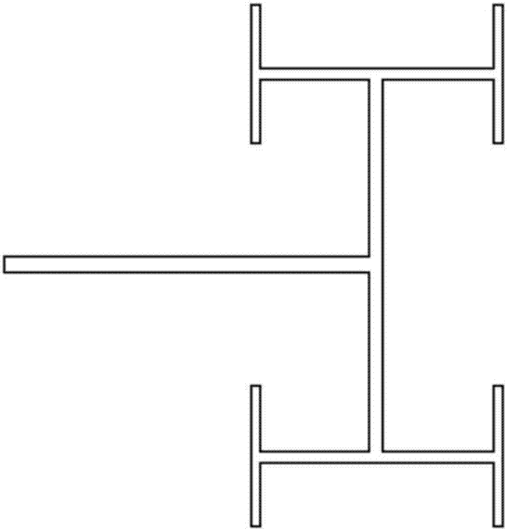
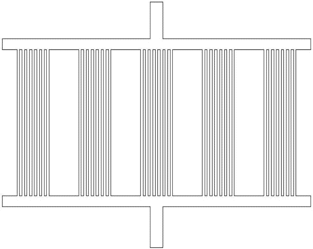
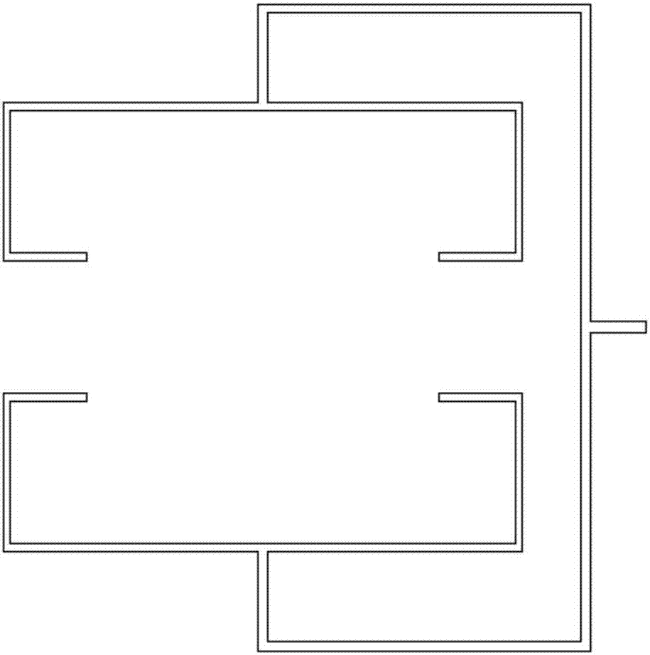
The invention discloses a micro-channel cold plate structure. The micro-channel cold plate structure comprises a substrate and a micro-flowing-channel network processed on the substrate; and the micro-flowing-channel network comprises a shunting structure, a partial micro-channel network and a confluence structure in a combined manner. The micro-channel cold plate structure has the beneficial effects as follows: reasonable flow deploying of a cooling working medium is realized through T-shaped flowing channels, and then heat transfer is strengthened by tree-like and parallel micro channels; finally, energy re-confluence is realized through inverse Y-shaped two-furcation flowing channels, so that high channel distribution uniformity is realized, and the network can be uniformly distributed in the whole to-be-dissipated region; the overall micro-fluid network is in all-parallel-connection way, so that high temperature consistency is achieved; the cooling working medium flows smoothly in the flowing channels, so that low flowing resistance is formed; and furthermore, the micro channels in each group of the partial micro-channel network are arranged in parallel, and the channels are more in branches and high in span, so that the process can be realized conveniently, partial pressure loss can be lowered, and the heat dissipation performance of the micro-channel cold plate can be further improved.

Description

technical field [0001] The invention belongs to the field of heat dissipation of electronic equipment, in particular to a microchannel cold plate structure for cooling phased array antennas. Background technique [0002] The trend of miniaturization of electronic devices is constantly urging the rapid development of microelectronics technology. Along with the continuous maturity of microfabrication technology, the improvement of chip performance and the strict limitation of device volume and weight, the number of electronic components in the same space has increased sharply. Thermal power consumption and heat flux are constantly increasing. Studies have shown that since the temperature rise exceeding the accommodation limit of electronic equipment is the main factor leading to its failure, efficient cooling of electronic equipment is the key to maintaining the stable and reliable operation of various functional modules and large electronic equipment systems. [0003] Radar,...

Claims


Application Information

Patent Timeline
Patent Type & Authority Applications(China)
IPC IPC(8): H01Q1/02
CPCH01Q1/02
Inventor 杜平安吴龙文谭慧卢婷陈加进王明阳
Owner UNIV OF ELECTRONICS SCI & TECH OF CHINA
Learn More