Magnetic field-adjustable low-power Hall thruster with magnetic shielding effect

A Hall thruster and shielding effect technology, applied in the field of electric propulsion, can solve the problems of increased wall corrosion, channel thickness thinning, and increased wall loss, and achieve the effects of reducing wall loss, prolonging life, and increasing life

Active Publication Date: 2017-09-15
BEIHANG UNIV
View PDF7 Cites 26 Cited by
  • Summary
  • Abstract
  • Description
  • Claims
  • Application Information

AI Technical Summary

Problems solved by technology

[0003] However, with the diversification of domestic aerospace mission requirements, the development of small satellites has received more and more attention, and more and more problems have been exposed in the process of reducing the power of Hall thrusters
As the size decreases, the ratio of the s

Method used


Image

  • Magnetic field-adjustable low-power Hall thruster with magnetic shielding effect
  • Magnetic field-adjustable low-power Hall thruster with magnetic shielding effect
  • Magnetic field-adjustable low-power Hall thruster with magnetic shielding effect

Examples


specific Embodiment approach 1

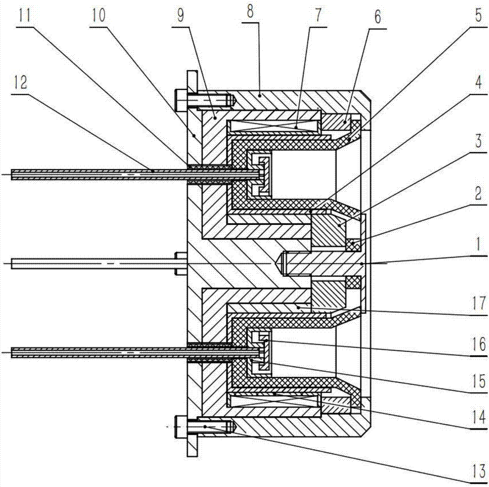
[0026] Embodiment 1: The present invention is a low-power Hall thruster with magnetic shielding effect with adjustable magnetic field. Channel 5, outer magnetic pole 6, fine-tuning magnetic coil 7, stainless steel shell 8, outer magnetic screen 9, cooling plate 10, insulating ceramic sleeve 11, air intake pipe 12, fixing screw 13, coil frame 14, distributor-lower bottom 15, Distributor - upper bottom 16, heat dissipation copper ring 17.

[0027] Insert four insulating ceramic bushings 11 into the 4mm diameter holes on the heat dissipation copper disc 10 .

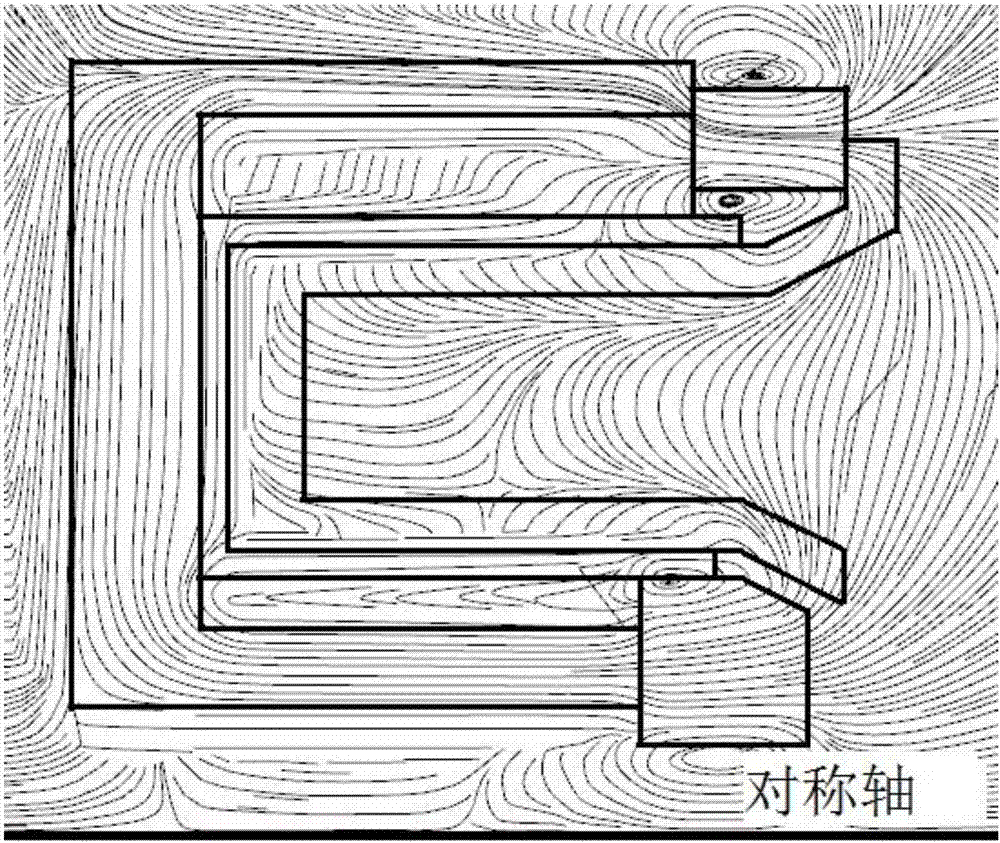
[0028] Taking the copper cooling plate 10 as a benchmark, the annular groove-shaped outer magnetic shield 9, the heat dissipation copper ring 17 and the annular groove-shaped inner magnetic shield 4 are set on the central axis of the heat dissipation copper plate 10 to heat the copper plate. The 10 planes are the left limit, and the four insulating ceramic bushings 11 are the circumferential limit. The heat dissipation co...

specific Embodiment approach 2

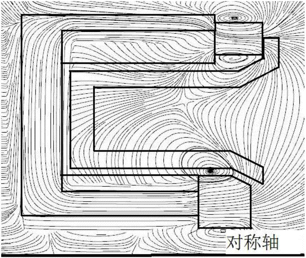
[0037] Embodiment 2: Compared with Embodiment 1, the inner magnetic shield 4 is deleted, and other structural forms are the same as Embodiment 1. A low-power magnetic field adjustable Hall thruster with weak magnetic shielding effect can be formed, and a comparative test is carried out. The magnetic field formed is as attached image 3 As shown, the magnetic field lines are mainly radial components, and the magnetic shielding effect is weak.

[0038] Ignition step of the present invention:

[0039] 1) The thruster of the present invention and the hollow cathode are fixed together on the test bench, and the circuit and the gas path are connected. 16) Act as anode and gas distributor for electric thruster;

[0040] 2) Hollow cathode power supply degassing activation;

[0041] 3) Supply xenon to the thruster and the hollow cathode respectively, and supply power to the anode of the thruster and the contact electrode of the hollow cathode;

[0042] 4) The hollow cathode heating...


PUM

PropertyMeasurementUnit
Residual magnetic inductionaaaaaaaaaa

Abstract

The invention discloses a magnetic field-adjustable low-power Hall thruster with a magnetic shielding effect, and belongs to the technical field of electric propulsion. Along with diversification of spaceflight task demands, more attention is paid to the low-power Hall thruster; but low power of the Hall thruster causes the problems of short life and low efficiency; and the problems are related to the geometric size of a discharge channel of the Hall thruster, the magnetic field configuration and strength and the like. The magnetic shielding theory is introduced in the design of the low-power Hall thruster; a permanent magnet is used for generating a high magnetic field; a double-magnetic-screen structure is used for forming a magnetic shielding magnetic field in the discharge channel to limit the plasma movement, so that the wall surface corrosion is weakened, and the life is prolonged; meanwhile, the power consumption of the Hall thruster is greatly reduced through use of the permanent magnet, and is not higher than 100 W; and in addition, the invention further designs a heat conduction structure in the thruster for preventing influence on the performance of the permanent magnet due to too high thermal load.

Description

Technical field: [0001] The invention belongs to the technical field of electric propulsion, and relates to a low-power Hall thruster with an adjustable magnetic field and a magnetic shielding effect. Background technique: [0002] Electric propulsion is an advanced propulsion method that converts electrical energy into kinetic energy of propellant to obtain thrust. Compared with traditional chemical propulsion methods, electric propulsion has the advantages of high specific impulse, high control precision, and long life. After 60 years of development, the international kilowatt-level Hall and ion electric propulsion technology has become increasingly mature. [0003] However, with the diversification of domestic aerospace mission requirements, the development of small satellites has received more and more attention, and more and more problems have been exposed in the process of reducing the power of Hall thrusters. As the size decreases, the surface area to volume ratio of...

Claims


Application Information

Patent Timeline
IPC IPC(8): F03H1/00
CPCF03H1/0031F03H1/0081F03H1/0075
Inventor 汤海滨张广川任军学姜逸伟王一白
Owner BEIHANG UNIV
Why Eureka
Try Eureka