
Anti-blocking type rotor wing heat accumulating type combustion device

A combustion device and rotary wing technology, applied in the combustion method, combustion type, lighting and heating equipment, etc., can solve the problems of pressure increase, difficult maintenance and replacement, descent, etc., to achieve the effect of improving efficiency and reducing maintenance time

Inactive Publication Date: 2017-09-15
西安昱昌环境科技有限公司
View PDF11 Cites 5 Cited by
  • Summary
  • Abstract
  • Description
  • Claims
  • Application Information

AI Technical Summary

Problems solved by technology

However, this kind of rotary RTO has the problem of dynamic sealing of the rotary valve. Since the rotary valve adopts a friction disc structure, the sealing gap between the stator and the rotor is too large to easily leak and affect the decomposition efficiency of the RTO, and the sealing gap between the stator and the rotor is too small to be easily worn and difficult to repair and replace. , there are also harmful gases that are difficult to handle with high viscosity and easy to scale; the supply heat storage body of the heat storage device is blocked or accumulated on the surface by oily matter or dirt, which cannot effectively perform heat exchange and cause a temperature drop
Contamination of the supply heat storage body of the heat storage device increases the pressure and affects the air flow inside the main body, thereby leading to an increase in the operating cost of the device or even failure

Method used


Image

  • Anti-blocking type rotor wing heat accumulating type combustion device
  • Anti-blocking type rotor wing heat accumulating type combustion device
  • Anti-blocking type rotor wing heat accumulating type combustion device

Examples


Embodiment Construction

[0024] The present invention will be further described below in conjunction with the accompanying drawings and specific embodiments.

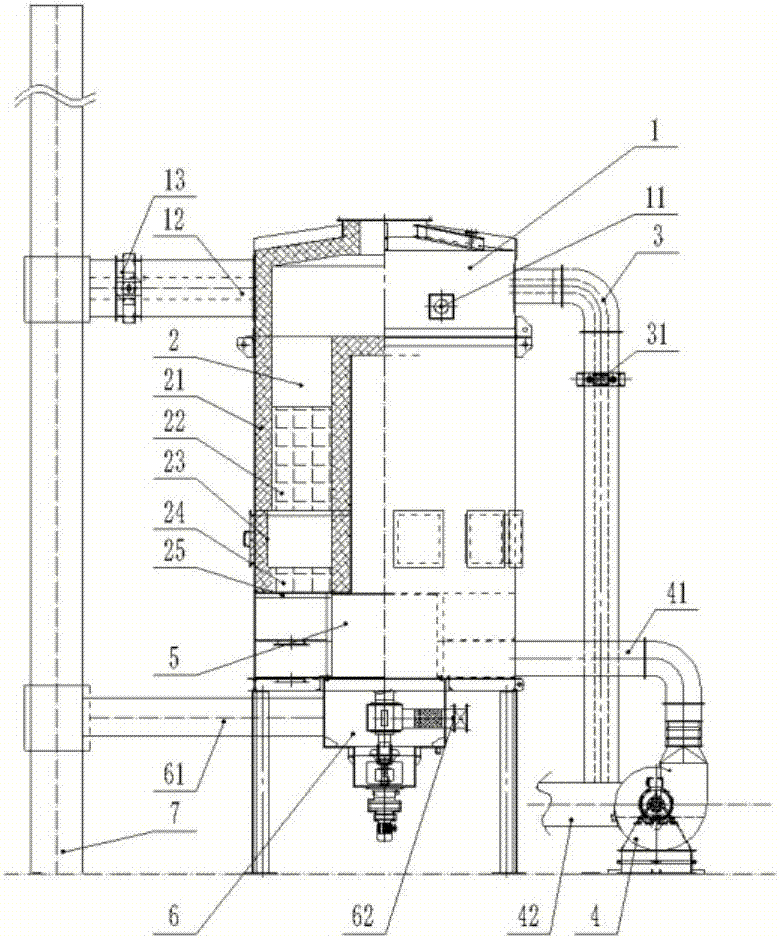
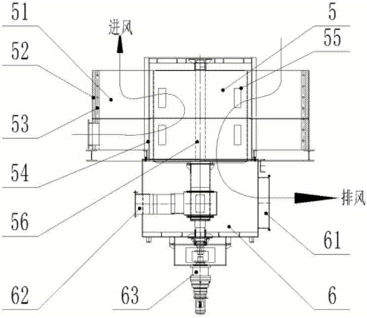
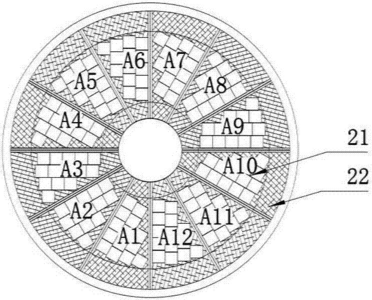
[0025] Such as Figure 1 ~ Figure 3 As shown, the present invention includes a combustion chamber 1 arranged on the top of the sealed shell, a heat storage layer 2 in the middle and a rotary valve at the bottom, the combustion chamber 1 communicates with the heat storage layer 2, and the combustion chamber 1 is provided with a The burner 11, the combustion chamber 1 communicates with the waste gas inlet pipe 40 through the preheating pipe 3, the preheating pipe 3 is an insulation pipe, the waste gas inlet pipe 40 is connected to the input end of the exhaust gas fan 4, and the output end of the exhaust gas fan 4 is connected to the exhaust gas The inlet pipe 41 communicates with the waste gas chamber, and the waste gas chamber communicates with the heat storage layer 2 through the waste gas channel on the rotary valve 5 .

[0026] The emergency...


PUM


Abstract

The invention discloses an anti-blocking type rotor wing heat accumulating type combustion device. The anti-blocking type rotor wing heat accumulating type combustion device comprises a combustion chamber arranged at the top of a sealing shell, a heat accumulating layer in the middle and a rotary valve at the bottom. The combustion chamber communicates with the heat accumulating layer. A combustor used for improving the temperature of the combustion chamber is arranged in the combustion chamber. The combustion chamber communicates with a waste gas inlet pipeline through a preheating pipeline. The waste gas inlet pipeline communicates with a waste gas cavity. The waste gas cavity communicates with the heat accumulating layer through a waste gas channel on the rotary valve. The combustion chamber communicates with the waste gas inlet pipeline through the preheating pipeline, the waste gas inlet pipeline communicates with the waste gas cavity, the preheating pipeline used for preheating waste gas is additionally arranged at the waste gas front end, and therefore organic volatile matter in the waste gas is prevented from being condensed before entering a furnace body; and an electric heating mechanism is additionally arranged on the rotary valve, and therefore the waste gas is in temperature rise all the time when entering the valve, and heat accumulating brick blocking caused by condensation is avoided.

Description

technical field [0001] The invention belongs to the field of combustion equipment during heat storage, and in particular relates to an anti-blocking rotary wing heat storage combustion device. Background technique [0002] The air compound pollution situation characterized by PM2.5 and O3 is severe in China. Volatile organic compounds (VOCs, Volatile Organic Compounds) are important precursors leading to O3 pollution and have an important impact on the formation of PM2.5. When the concentration of VOCs in the air exceeds a certain concentration, the human body will have headaches and weak nerve toxicity. The treatment of VOCs has become a major environmental problem that needs to be solved urgently in the country. Therefore, the harmful gases can only be discharged after the treatment reaches the standard. Combustion equipment (RTO, regenerative thermaloxidizer system), which can perform pyrolysis treatment on harmful gases. Regenerative oxidation equipment has developed fr...

Claims


Application Information

Patent Timeline
IPC IPC(8): F23G7/06
CPCF23G7/06F23G2209/14
Inventor 任玲辉苏翔宇张涛张兴旺刘文涛
Owner 西安昱昌环境科技有限公司
Learn More