Efficient and energy-saving heat supply system adopting heat-conducting oil conduction

A heating system, high-efficiency and energy-saving technology, applied in heating systems, electric heating systems, heating fuels, etc., can solve the problems of fragile vacuum glass tubes, furnace ash garbage, air pollution, etc., and achieve low equipment investment and high heat utilization The effect of high efficiency and flexible installation

Inactive Publication Date: 2017-09-15
辽宁易通智能装备制造有限公司
View PDF6 Cites 2 Cited by
  • Summary
  • Abstract
  • Description
  • Claims
  • Application Information

AI Technical Summary

Problems solved by technology

[0003] The existing heat transfer oil systems are coal-fired boilers, solar hot water boilers, ground source heat pumps, and electric heating membranes. However, these have corresponding shortcomings. Burning coal, producing air pollution and ashes, and requires professional care; solar hot water boilers: need a large enough space, vacuum glass tubes are fragile, and need artificial snow removal or electric heating assistance in winter; ground source heat pumps: need Professionals dig deep wells and need high-power circulating pumps; electric heating membranes: they need to be preset before decoration, and have a service life of 6 years, and they need to be redecorated after 6 years

Method used


Image

  • Efficient and energy-saving heat supply system adopting heat-conducting oil conduction

Examples


Embodiment

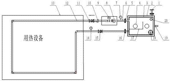
[0020] As shown in the figure, it is a schematic diagram of the structure and composition of the heat transfer system of the present invention. The outer tank 2 of the heat transfer oil tank is filled with thermal insulation cotton, so that the heat transfer oil in the inner tank 3 of the oil tank is heated by the heat transfer oil heating tube 4, so that the oil in the oil tank reaches the set value. Fixed temperature, and can control the temperature, over-temperature alarm. Through the oil pump 8, the oil in the oil tank is output through the oil outlet 5 of the oil tank, and the outlet pressure of the oil tank can be observed through the pressure gauge 7. After passing through the oil well pump 8, the oil outlet explosion-proof thermometer 9 can monitor the temperature of the oil outlet pipe at any time, and through the Y-type filter 10 Filter impurities and enter the heating equipment pipeline 12 through the ball valve 11 to reach the heating equipment 13. The heating equip...


PUM


Abstract

The invention discloses an efficient and energy-saving heat supply system adopting heat-conducting oil conduction, and relates to a heat supply system. The heat supply system comprises a magnetic flap level gauge (1), an outer tank (2) of an oil tank, an inner tank (3) of the oil tank, a heat-conducting oil heating pipe (4), an oil outlet port (5) of the oil tank, an oil outlet pipe (6), a pressure gauge (7), an oil suction pump (8), an anti-explosive oil outlet temperature gauge (9), a Y-type filter (10), a ball valve (11), a pipeline (12) for entering heat utilization equipment, the heat utilization equipment (13), an anti-explosive oil return temperature gauge (14), another ball valve (15), an oil inlet port (16), a partition (17) of the oil tank, a vacuum safety cap (18), an oil drainage positive thread end (19) and an oil injection positive thread end (20), wherein the interior of the oil cavity of the oil tank and the oil suction pump (8) are communicated to the heat utilization equipment (13), and the partition (17) of the oil tank is arranged in the oil tank. According to the heat supply system disclosed by the invention, an oil circulation pump is used for carrying out forced liquid phase circulation, heat energy is conveyed to the heat utilization equipment and then returned for re-heating, and the heat supply system is less in pollution, high in heat utilization rate, safe, and free from pollution discharge, pollution and heat pollution.

Description

technical field [0001] The invention relates to a heat supply system, in particular to a heat supply system conducted by heat transfer oil with high efficiency and energy saving. Background technique [0002] The heat conduction system is to insert the heat conduction oil electric heating tube directly into the organic carrier (heat conduction oil) for direct heating, and use the circulation pump to force the heat conduction oil to circulate in the liquid phase, and transfer the heat to one or more heat-consuming equipment. After unloading, it passes through the circulation pump again, returns to the oil tank, absorbs the heat, and transfers it to the heat-consuming equipment. This cycle repeats to realize the continuous transfer of heat, so that the temperature of the heated object rises to meet the heating process requirements. The heat conduction oil heater adopts a digital display temperature controller to control the temperature, and has functions such as over-temperatu...

Claims


Application Information

Patent Timeline
Patent Type & Authority Applications(China)
IPC IPC(8): F24D13/04F24D19/10
CPCF24D13/04F24D19/1096F24D2200/08
Inventor 邹彬彬
Owner 辽宁易通智能装备制造有限公司
Why Eureka
Try Eureka