

Multi-mechanical arm intra-operative radiation treatment device
A radiotherapy and robotic arm technology, applied in the field of radiotherapy medicine, can solve problems such as time-consuming, complicated steps, and inability to determine the position, angle, and direction of lesions, and achieve the effect of saving treatment time, reducing risks, and reducing the burden on clinicians
- Summary
- Abstract
- Description
- Claims
- Application Information
AI Technical Summary
Problems solved by technology
Method used
Image

Examples
Embodiment Construction
[0034] In order to make the technical means, creative features, goals and effects achieved by the present invention easy to understand, the present invention will be further described below in conjunction with specific illustrations.
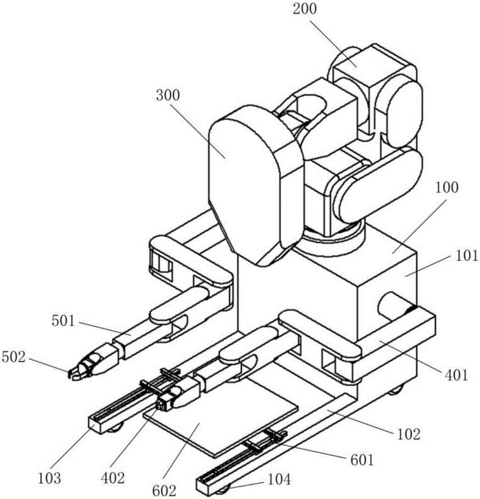
[0035] figure 1 It shows a multi-manipulator intraoperative radiation therapy device in an initial stowed state according to an embodiment of the present invention, so as to facilitate the delivery of the multi-manipulator intraoperative radiation therapy device.
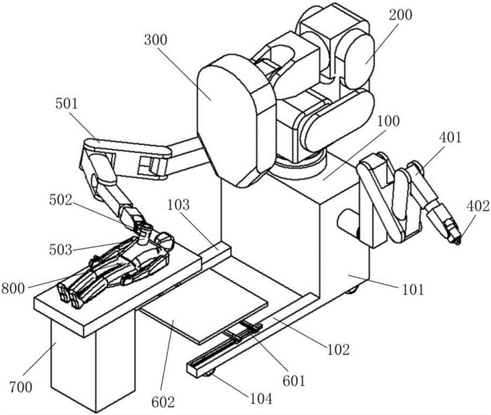
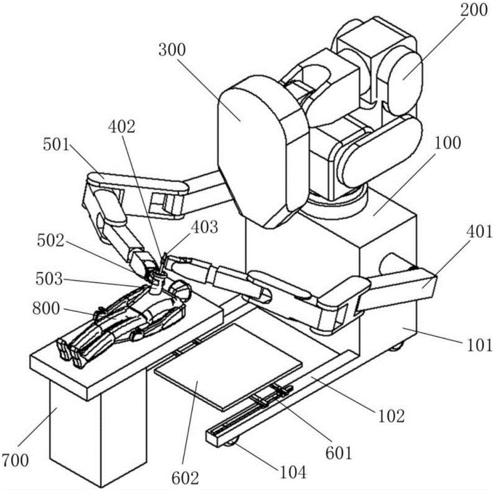
[0036] Such as figure 1 As shown, the multi-manipulator intraoperative radiotherapy device according to an embodiment of the present invention includes: a base 100, a main manipulator 200, a linear accelerator radiation head 300, a left manipulator 401, a left manipulator end gripper 402, The right mechanical arm 501 , the gripper 502 at the end of the right mechanical arm, the two-dimensional motion platform 601 , and the ray blocker 602 .
[0037] The base 100 includes a base body...
PUM
 Abstract
Description
Claims
Application Information