Map making method, device and system based on laser radar

A laser radar and map technology, applied in the field of data processing, can solve the problem of low accuracy of the output map, achieve the effect of improving registration accuracy and accuracy, high accuracy, and saving manufacturing costs

Active Publication Date: 2017-09-19
BEIJING GREEN VALLEY TECH CO LTD
View PDF5 Cites 22 Cited by
  • Summary
  • Abstract
  • Description
  • Claims
  • Application Information

AI Technical Summary

Problems solved by technology

[0005] The purpose of the embodiment of the present invention is to provide a mapping method, device and system based on lidar to solve the problem of low accuracy of the output map of the mobile mapping system based on lidar and SLAM technology

Method used


Image

  • Map making method, device and system based on laser radar
  • Map making method, device and system based on laser radar
  • Map making method, device and system based on laser radar

Examples


Embodiment 1

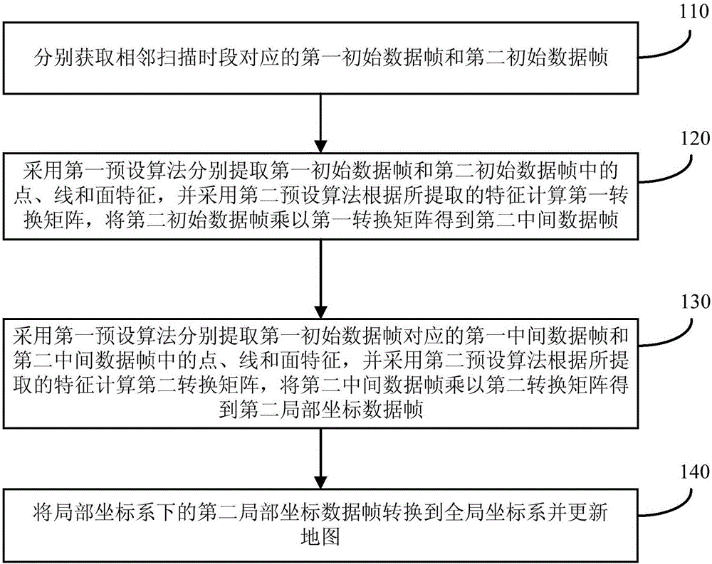
[0033] figure 1 A schematic flow chart of a lidar-based mapping method provided in Embodiment 1 of the present invention, the method can be executed by a lidar-based mapping device, wherein the device can be implemented by software and / or hardware, and generally can be integrated in the laser radar scanning system. like figure 1 As shown, the method includes:

[0034] Step 110, respectively acquire the first initial data frame and the second initial data frame corresponding to adjacent scanning periods.

[0035] Wherein, the initial data frame includes the point cloud data scanned by the lidar and the navigation data collected by the inertial measurement unit, the scanning period corresponding to the first initial data frame is before the scanning period corresponding to the second initial data frame, and the The sequence number of the first initial data frame is greater than 1.

[0036]Exemplarily, the lidar-based mapping device can be integrated into the storage control ...

Embodiment 2

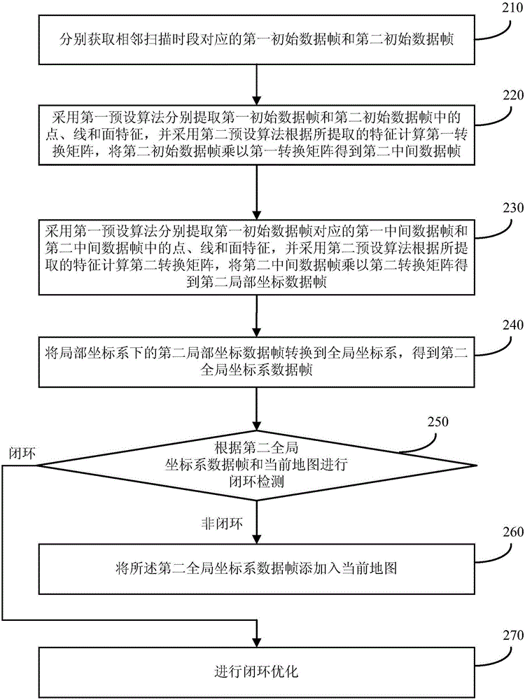
[0060] figure 2 It is a schematic flow chart of a lidar-based mapping method provided by Embodiment 2 of the present invention. This embodiment is optimized based on the above-mentioned embodiments, such as figure 2 As shown, the method of the present embodiment includes the following steps:

[0061] Step 210, acquiring first initial data frames and second initial data frames corresponding to adjacent scanning periods respectively.

[0062] Wherein, the initial data frame includes the point cloud data scanned by the lidar and the navigation data collected by the inertial measurement unit, the scanning period corresponding to the first initial data frame is before the scanning period corresponding to the second initial data frame, and the The sequence number of the first initial data frame is greater than 1.

[0063] Step 220, using the first preset algorithm to extract the point, line and surface features in the first initial data frame and the second initial data frame re...

Embodiment 3

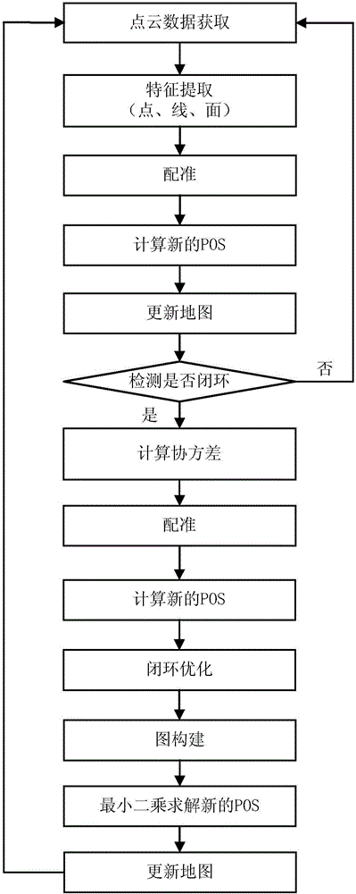
[0090] Embodiment 3 of the present invention provides a specific preferred implementation manner on the basis of the foregoing embodiments. image 3 It is a schematic flowchart of a lidar-based mapping method provided by Embodiment 3 of the present invention.

[0091] (1) Start a thread to collect data packets of lidar from the network port.

[0092] (2) A thread receives the lidar data packet, and converts the data into a point cloud data format containing X, Y, Z and time information after each data reception.

[0093] (3) A thread collects IMU data from the serial port.

[0094] (4) A thread extracts point, line, and surface features according to curvature and performs matching.

[0095] Suppose the current scan data is P k , the next scan data is P k+1 , and both scan data are available, from P k+1 Point, line and surface features are extracted from them, denoted as F k1+1 , F k2+1 and F k3+1 , at P k Find the corresponding point, line and surface features in , de...


PUM


Abstract

An embodiment of the invention discloses a map making method, device and system based on laser radar. The method comprises: respectively acquiring two preliminary data frames which correspond to adjacent scanning periods; respectively extracting point, line and surface features in the two preliminary data frames by a first preset algorithm; calculating a first transfer matrix by a second preset algorithm according to the extracted features; implementing registration of the two preliminary data frames; respectively extracting point, line and surface features of two middle data frames by the first preset algorithm and implementing registration again; and transforming local coordinate data frames, which are obtained by secondary registration, under a local coordinate system to a global coordinate system and updating the map. According to the technical scheme in the embodiment, the precision and accuracy of the obtained map can be improved, the map drawing efficiency is improved, and the occupied space and manufacturing cost of the system are saved.

Description

technical field [0001] Embodiments of the present invention relate to the technical field of data processing, and in particular to a method, device and system for mapping based on lidar. Background technique [0002] At present, the mobile mapping system has shown broad application prospects in the fields of forestry resource investigation, traffic facility monitoring, and tunnel surveying. Global Positioning System (Global Positioning System, GPS) and Inertial Measurement Unit (Inertial Measurement Unit, IMU, also known as inertial navigation system) integrated navigation is almost the standard configuration of mainstream mobile mapping systems, but these systems are in the case of GPS signal failure It's hard to work effectively. [0003] SLAM (Simultaneous Localization and Mapping, simultaneous positioning and mapping) technology can overcome the above shortcomings, and at the same time reduce the overall cost of the 3D mapping system. The application of SLAM technology...

Claims


Application Information

Patent Timeline
Patent Type & Authority Applications(China)
IPC IPC(8): G01C21/32G01C21/20G01S17/02G01S17/89G01S17/86
CPCG01C21/20G01C21/32G01S17/02G01S17/42G01S7/4808G01S17/89G01S17/86G06F17/11G06F17/16G06F16/29G06F18/21
Inventor 郭彦明
Owner BEIJING GREEN VALLEY TECH CO LTD
Why Eureka
Try Eureka