Resonance circuit

A resonant circuit and resonant capacitor technology, applied in the direction of electrical components, adjusting electrical variables, high-efficiency power electronic conversion, etc., can solve the problems of low operating frequency, increased operating frequency, and reduced output power of LLC resonant circuits, and avoid Feedback signal transmission, work efficiency improvement, high work efficiency effect

Pending Publication Date: 2017-09-22
桐庐恒英电子有限公司
View PDF10 Cites 6 Cited by
  • Summary
  • Abstract
  • Description
  • Claims
  • Application Information

AI Technical Summary

Problems solved by technology

[0004] However, in the prior art, in the normal operating range of the LLC resonant circuit, as the operating frequency increases, the gain of the resonant circuit decreases, and the output power decreases. It can be seen that the existing LLC Resonant circuit, its operating frequency will increase as the load power decreases, so that its maximum operating frequency is limited, making the full-load operating frequency of the LLC resonant circuit relatively low
Moreover, in the prior art, in order to ensure the output constant current or output constant voltage, it is necessary to collect the output voltage or output current of the secondary side as a feedback signal, which leads to the need to use an optocoupler to feed back the feedback signal to the control circuit, and its cost is relatively high. high

Method used


Image

  • Resonance circuit
  • Resonance circuit
  • Resonance circuit

Examples


Embodiment Construction

[0041] The following will clearly and completely describe the technical solutions in the embodiments of the present invention in conjunction with the accompanying drawings in the embodiments of the present invention. Obviously, the described embodiments are only some of the embodiments of the present invention, not all of them. Based on the embodiments of the present invention, all other embodiments obtained by persons of ordinary skill in the art without making creative efforts belong to the protection scope of the present invention.

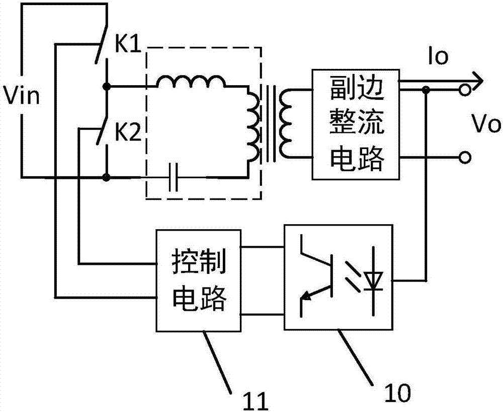
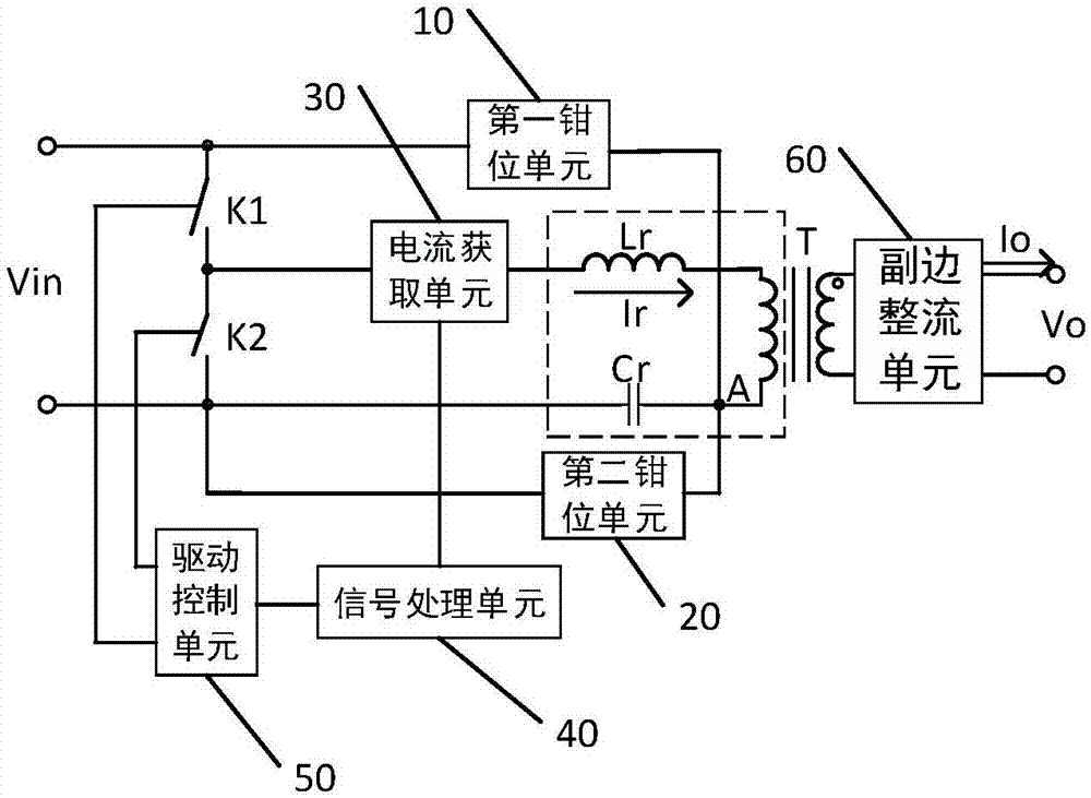
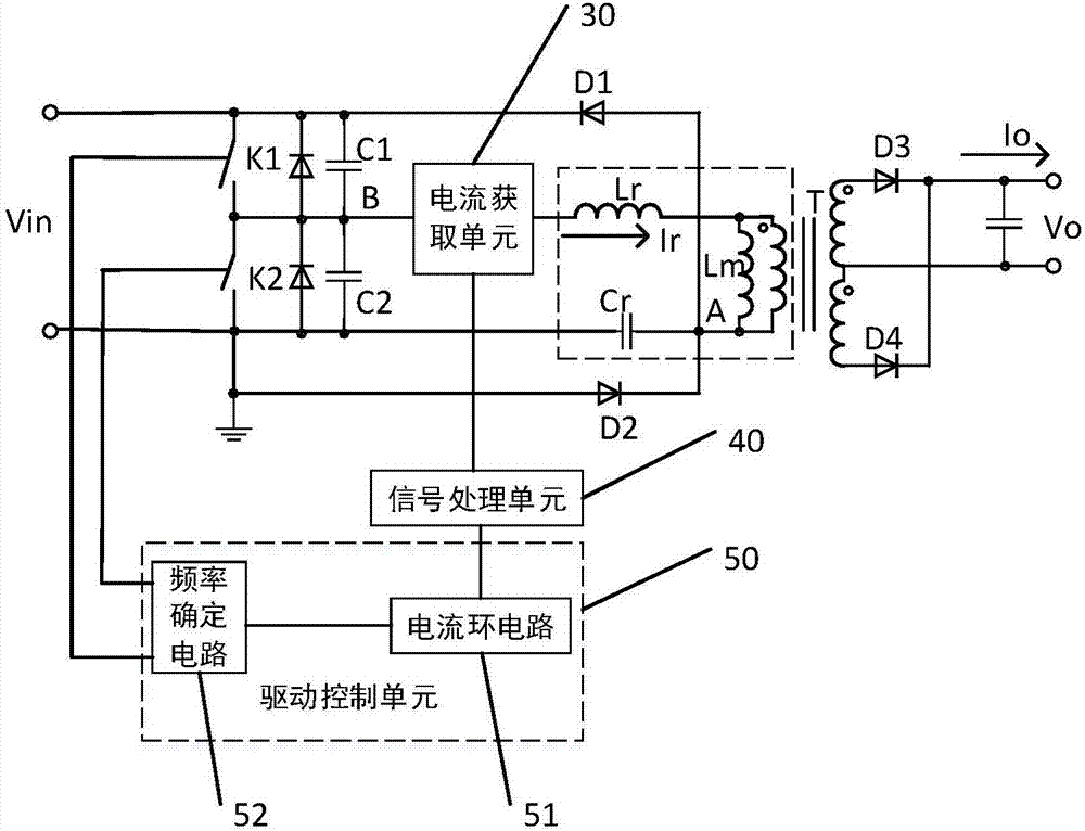
[0042] The object of the present invention is to provide a resonant circuit whose working frequency increases with the increase of output power and the working efficiency is significantly improved under the condition of low cost.

[0043] There are many kinds of resonant circuits such as LLC resonant circuit and LCC resonant circuit. In order to enable those skilled in the art to better understand the solution of the present invention, the follo...


PUM


Abstract

The invention discloses a resonance circuit, which comprises a switch unit, a resonant unit, a transformer and a secondary rectifier unit, wherein the resonant unit comprises a resonant capacitor and a resonant inductor; the resonance circuit further comprises a current acquisition unit, a signal processing unit, a drive control unit, a first clamping unit and a second clamping unit; a first end and a first reference voltage end of the first clamping unit are connected; a first end and a second reference voltage end of the second clamping unit are connected; a second end of the first clamping unit and a second end of the second clamping unit are both connected to a public end of the resonant capacitor and a primary winding of the transformer; an input end of the current acquisition unit is connected to the resonant inductor; an output end of the current acquisition unit is connected to an input end of the signal processing unit; and an output end of the signal processing unit is connected to an input end of the drive control unit. When the cost of the resonance circuit is smaller, the working frequency of the resonance circuit is increased along with the increase of the output power, so that the working frequency of the resonance circuit is further improved.

Description

technical field [0001] The invention relates to the field of electronic circuits, in particular to a resonant circuit. Background technique [0002] In the design of the resonant circuit of the power converter, if high-frequency operation can be used, the size of the transformer can be greatly reduced, the power density can be increased, and the work efficiency can be improved. Of course, while improving the working efficiency, it should also ensure the output of constant current, constant voltage or constant power output. [0003] like figure 1 as shown, figure 1 An LLC resonant circuit diagram provided for the prior art, the LLC resonant circuit converts the input voltage Vin into the form required by the load, mainly through the electrical signal acquisition circuit (not shown) for the output voltage Vo or output current Io of the secondary side Sampling, comparing the sampling signal with the reference signal, and generating a feedback signal from the comparison resul...

Claims


Application Information

Patent Timeline
Patent Type & Authority Applications(China)
IPC IPC(8): H02M3/335
CPCH02M3/33523H02M3/33569H02M1/0058Y02B70/10
Inventor 梅进光姜德来杨军
Owner 桐庐恒英电子有限公司
Why Eureka
Try Eureka