
System for preparing urea solution for denitration

A urea and solution technology, applied in the directions of dissolution, mixer accessories, mixers, etc., can solve the problems of high power consumption, water consumption and steam consumption, low degree of automation, poor operating environment, etc., to reduce comprehensive energy consumption and labor intensity. , The effect of reducing equipment cost

Inactive Publication Date: 2017-09-26
SHANDONG AONENG ELECTRIC POWER SCI & TECH
View PDF0 Cites 0 Cited by
  • Summary
  • Abstract
  • Description
  • Claims
  • Application Information

AI Technical Summary

Problems solved by technology

[0005] In response to this situation, domestic and foreign have discovered and utilized the characteristics of urea decomposition to produce ammonia, and used urea decomposition or hydrolysis instead of liquid ammonia for denitrification. However, due to immature technology and foreign monopoly, the equipment investment is very large, 300- The investment in urea hydrolysis and urea pyrolysis equipment with 350kg / h ammonia production capacity is 30-70 million. The degree of automation is low, and a large amount of urea solution needs to be manually configured regularly and stored for production use; power consumption, water consumption, and steam consumption are high. During the solution process, the ammonia leakage is serious, the solution preparation room has a strong ammonia smell, and the operating environment is poor

Method used


Image

  • System for preparing urea solution for denitration

Examples


Embodiment Construction

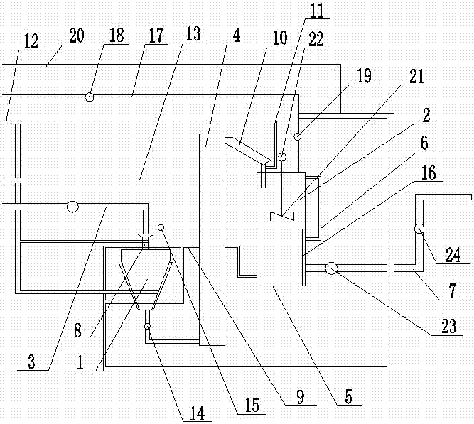
[0021] Accompanying drawing is a kind of specific embodiment of the present invention. This embodiment includes a hopper 1 and a liquid distribution tank 2, an automatic feeding device 3 is connected to the top of the hopper 1, a urea delivery device 4 is installed between the bottom of the hopper 1 and the liquid distribution tank 2, and a liquid storage tank 5 is arranged below the liquid distribution tank 2 , the liquid distribution tank 3 and the liquid storage tank 5 are connected through an automatic overflow device 6, the bottom of the liquid storage tank 5 is connected with a urea solution output pipeline 7, and a cylindrical connecting section 8 is provided between the hopper 1 and the automatic feeding device 3, The cylindrical connecting section 8 and the inside of the hopper 1 are respectively connected to the bottom of the liquid storage tank 5 through the heating hot water pipeline 9 . A dosing feed chute 10 is provided between the end of the urea delivery device...


PUM


Abstract

The invention relates to a system for preparing a solution, in particular to a system for preparing a urea solution for denitration. The system for preparing the urea solution for denitration comprises a hopper and a solution preparation tank, and is characterized in that the top of the hopper is connected with an automatic feeding device, a urea conveying device is installed between the bottom of the hopper and the solution preparation tank, a liquid storage tank is arranged under the solution preparation tank, the solution preparation tank is connected with the liquid storage tank by means of an automatic overflow device, the bottom of the liquid storage tank is connected with a urea solution output pipeline, a cylinder connecting section is arranged between the hopper and the automatic feeding device, and the cylinder connecting section and the interior of the hopper are respectively connected with the bottom of the liquid storage tank by means of a heat tracing hot water pipeline. The system has the beneficial effects of being less in running heat loss, less in investment, simple to operate, fewer in associated equipment and high in degree of automation.

Description

(1) Technical field [0001] The invention relates to a solution preparation system, in particular to a urea solution preparation system for denitrification. (2) Background technology [0002] NO X Appearing as a harmful gas in the industrial production of thermoelectricity, ceramic glass, coking, cement and other industries, it has great harm to the normal atmospheric environment, and it can directly cause acid rain and toxic smog. Therefore, the NO in the flue gas in the production device X There are relatively large restrictions, and denitrification is particularly important. In recent years, traditional NO removal methods used in thermal power, coking, cement, ceramic glass and other industries X There are methods such as SNCR and SCR. These methods all require corresponding denitrification reducing agents. [0003] The choice of denitrification reducing agent is generally considered comprehensively in terms of its physical properties, economy and safety. At present, ...

Claims


Application Information

Patent Timeline
Patent Type & Authority Applications(China)
IPC IPC(8): B01F3/12B01F15/00B01F15/04B01D53/56
CPCB01D53/56B01D2251/2067B01F23/53B01F35/2112B01F35/2211B01F35/2215B01F35/833B01F2101/48
Inventor 刘梦冉蒋胜昔袁栋鲁妍
Owner SHANDONG AONENG ELECTRIC POWER SCI & TECH
Learn More