
Large-capacity dry-type high-frequency high-voltage transformer

A high-frequency, high-voltage, transformer technology, used in fixed transformers or mutual inductance, transformer/inductor cooling, transformer/inductor cores, etc., to solve problems such as long-term reliability, small transfer capacity, and low boost voltage. , to achieve the effect of ensuring high-frequency insulation level, excellent dielectric properties, and high voltage output

Pending Publication Date: 2017-09-26
FUJIAN NEWLAND ENTECH CO LTD
View PDF0 Cites 1 Cited by
  • Summary
  • Abstract
  • Description
  • Claims
  • Application Information

AI Technical Summary

Problems solved by technology

[0013] The purpose of the present invention is to provide a large-capacity dry-type high-frequency high-voltage transformer, which is used to solve the performance defects of small transmission capacity, low boost voltage, low efficiency, inability to operate for a long time and low reliability in the current high-frequency and high-voltage field. , so that the use of high-frequency high-voltage power supply can be more extensive and reliable; the high-frequency high-voltage power supply can also achieve large-capacity high-voltage output, high-efficiency output, long-term uninterrupted operation, small size, light weight, and excellent performance of low loss and heat generation

Method used


Image

  • Large-capacity dry-type high-frequency high-voltage transformer
  • Large-capacity dry-type high-frequency high-voltage transformer
  • Large-capacity dry-type high-frequency high-voltage transformer

Examples


Embodiment 1

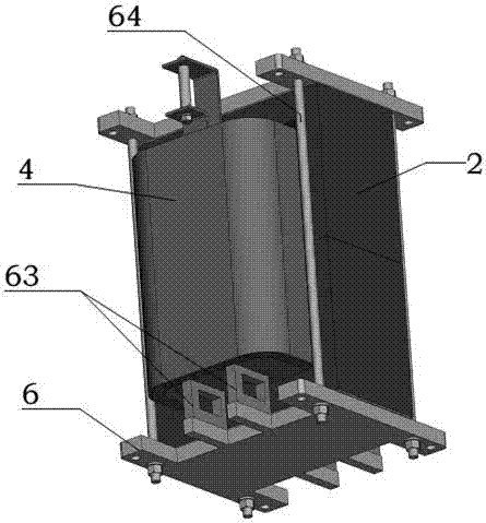
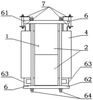
[0072] as attached Figure 1-13 As shown, the large-capacity dry-type high-frequency high-voltage transformer 1 of the present invention includes: an EE-type magnetic core 2, a square frame 3, a square coil 4, a fixed support device 6, and a copper bar or copper wire 7 for the coil. As shown in Figure 5, the EE-shaped magnetic core 2 is formed by two E-shaped magnetic cores 21 facing each other with openings aligned up and down. A closed magnetic circuit is formed between the upper and lower bottom yokes 22 , the middle column 23 and the side columns 24 of the EE-type magnetic core.

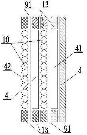
[0073] The square frame 3 is set on the center column 24 of the EE-type magnetic core 2, the square coil 4 is a vertical structure, and is wound on the square frame 3 by a combination of a low voltage coil 41 and a high voltage coil 42. The square coil 4 Axial heat dissipation air passage 5 is set in the heat dissipation air passage 5, and air passage stay 8 is arranged in the heat dissipation a...


PUM


Abstract

The invention provides a large-capacity dry-type high-frequency high-voltage transformer. The transformer comprises an EE-type magnetic core, a frame, coils and a fixing and supporting device, and further comprises cooper bars or copper wires containing the coils; the EE-type magnetic core is formed by installing two E-type magnetic core bodies with opposite openings in an up-down alignment mode, and the frame is installed on a middle column of the EE-type magnetic core in a sleeving mode; the coils are of vertical structures and wind on the square frame through the combination of low-voltage coil bodies and high-voltage coil bodies in a mutually staggered mode, insulating layers are arranged between the adjacent low-voltage coil bodies and high-voltage coil bodies, the high-voltage coil bodies are prepared by winding large-strand litz wires, and the large-strand litz wires are prepared by twisting a plurality of small-strand litz wires; the fixing and supporting device comprises an upper epoxy plate, a lower epoxy plate, a support plate and a pull rod, the EE-type magnetic core is located on the lower epoxy plate, the coils are located on the support plate, the lower epoxy plate is fixedly connected to the support plate, the upper epoxy plate is fixedly connected to the lower epoxy plate through the pull rod, and minning edges are arranged on gaps between the upper and lower end portions of the coils and the EE-type magnetic core.

Description

technical field [0001] The invention belongs to the field of dry-type transformers and belongs to high-voltage electrical equipment, in particular to a large-capacity dry-type high-frequency high-voltage transformer. Background technique [0002] Existing conventional transformers have more or less the following technical shortcomings, resulting in the existing high-frequency high-voltage transformers having small transfer capacity (below 10kVA), low boost voltage (below 1000V), low efficiency (below 90%), and incapable of long-term Insufficient technology for poor operation and reliability. [0003] 1. The winding method of conventional transformers is relatively uniform. Basically, the low-voltage coil is wound first, and then the high-voltage coil is wound outside the low-voltage coil. There is nothing wrong with this design method in the field of medium and low frequencies. However, in the field of large-capacity high-frequency transformers, this method will cause a ph...

Claims


Application Information

Patent Timeline
IPC IPC(8): H01F27/24H01F27/30H01F27/28H01F27/08H01F27/32H01F19/04
CPCH01F27/24H01F27/2823H01F27/2876H01F27/306H01F27/324H01F19/04
Inventor 张良波陈滢
Owner FUJIAN NEWLAND ENTECH CO LTD
Learn More