CO2 (carbon dioxide) purifying system and gas treatment system

A gas pipeline and reverse degassing technology, which is applied in the field of CO2 purification system and gas treatment system, can solve the problems of prolonged production time, unfavorable installation of skids, increased probability of failure of various parts of the valve, etc., so as to reduce the pressure swing adsorption cycle. Time, reduce equipment investment cost, reduce equipment cost investment effect

Active Publication Date: 2017-09-29
CHENGDU SEPMEM SCI & TECH
View PDF18 Cites 1 Cited by
  • Summary
  • Abstract
  • Description
  • Claims
  • Application Information

AI Technical Summary

Problems solved by technology

[0002] Purification of CO by Pressure Swing Adsorption 2 Because the system contains many operating steps, the number of program-controlled valves is very large, which increases the investment cost and equipment installation cost of the entire device, and the valve rack area occupies a large area, which is not conducive to the prying of the device.
[0003] Purification of CO by Pressure Swing Adsorption 2 Due to the short cycle time of the system, the switching frequency of the program-controlled valve is high, and the failure probability of each component of the valve is greatly increased.
At the same time, during the pressure balance process of pressure swing adsorption, the valve core is washed by high-speed air flow, and the valve sealing surface is easily damaged, causing internal leakage of the valve, affecting the operation of the device, increasing the daily maintenance cost and difficulty of repairing the device, and prolonging the production time. increased production costs
[0004] Purification of CO from current pressure swing adsorption 2 From the perspective of the operation of the device, the failure of the program-controlled valve or internal leakage of the sealing surface is the biggest bottleneck affecting the stable operation of the entire device
Although the service life of the programmable valve can be extended by improving the valve design and optimizing the structure of the sealing surface, the problems of the fault of the programmable valve and internal leakage of the sealing surface cannot be avoided fundamentally
[0005] Normally, CO 2 In the adsorption process, the adsorption operation time is short (less than one second). Such a short time requires that the program-controlled valve must be able to respond quickly, which has very high requirements for the program-controlled valve, which greatly increases the cost of the program-controlled valve.

Method used


Image

  • CO2 (carbon dioxide) purifying system and gas treatment system
  • CO2 (carbon dioxide) purifying system and gas treatment system
  • CO2 (carbon dioxide) purifying system and gas treatment system

Examples


Embodiment

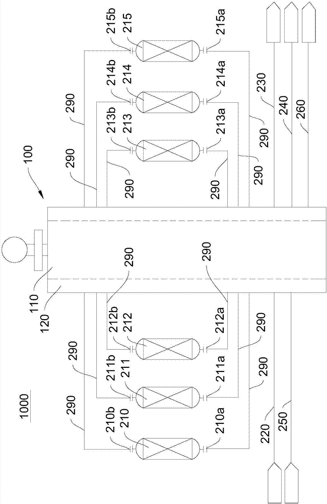
[0041] Please refer to figure 1 , this embodiment provides a CO 2 Purification system 1000, CO 2 The purification system 1000 includes a rotary valve 100 , an adsorption tower unit (not shown in the figure), a feed gas pipeline 220 , a non-adsorbed gas pipeline 230 , a reverse deflation pipeline 240 , a final gas charging pipeline 250 and an evacuation pipeline 260 .

[0042] The feed gas pipeline 220 , the non-adsorbed gas pipeline 230 , the reverse deflation pipeline 240 , the final gas filling pipeline 250 , the evacuation pipeline 260 and the adsorption tower unit are all connected to the rotary valve 100 . It should be noted, figure 1 Only the connection relationship between the above-mentioned various pipelines and the various interfaces of the adsorption tower unit and the rotary valve 100 is shown, figure 1 It is a schematic diagram of the connection relationship, and does not limit the location of the connection.

[0043] The rotary valve 100 can selectively conne...


PUM


Abstract

The invention discloses a CO2 (carbon dioxide) purifying system and a gas treatment system, and relates to the technical field of CO2 purifying. The CO2 purifying system comprises a raw gas pipeline, a non-adsorbing gas pipeline, a reverse gas bleeding pipeline, a rotary valve and an adsorption tower, wherein the rotary valve comprises a non-rotary part and a rotary part; the non-rotary part is provided with a first flow passage, and the rotary part is provided with a second flow passage; the rotary part is rotated to enable the second flow passage to selectively communicate the raw gas pipeline, the non-adsorbing gas pipeline, the reverse gas bleeding pipeline and the adsorption tower. The gas treatment system comprises the CO2 purifying system. The CO2 purifying system and the gas treatment system have the advantage that multiple pipelines are controlled by one rotary valve, so that the cost is reduced, and the control is convenient.

Description

technical field [0001] The present invention relates to CO 2 The technical field of purification, in particular, relates to a CO 2 Purification system and gas treatment system. Background technique [0002] Purification of CO by Pressure Swing Adsorption 2 Because the system includes many operating steps, the number of program-controlled valves is very large, which increases the investment cost and equipment installation cost of the entire device, and the valve rack area occupies a large area, which is not conducive to the prying of the device. [0003] Purification of CO by Pressure Swing Adsorption 2 Due to the short cycle time of the system, the switching frequency of the program-controlled valve is high, and the failure probability of each component of the valve is greatly increased. At the same time, during the pressure balance process of pressure swing adsorption, the valve core is washed by high-speed air flow, and the valve sealing surface is easily damaged, caus...

Claims


Application Information

Patent Timeline
Patent Type & Authority Applications(China)
IPC IPC(8): B01D53/047C01B32/50
CPCB01D53/0473B01D2259/40005B01D2259/40007Y02C20/40
Inventor 张惊涛王振
Owner CHENGDU SEPMEM SCI & TECH
Why Eureka
Try Eureka