
Mechanical arm mechanism for industrial robot
A technology of industrial robots and manipulators, which is applied in the direction of manipulators, manufacturing tools, chucks, etc., can solve the problems of complex finger structure transmission structure, affecting handling efficiency, inconvenient maintenance, etc., to ensure normal handling, simple finger structure and transmission structure, low cost effects
- Summary
- Abstract
- Description
- Claims
- Application Information
AI Technical Summary
Problems solved by technology
Method used
Image

Examples
Embodiment Construction
[0017] In order to more clearly illustrate the technical solutions in the embodiments of the present invention or the prior art, the following will briefly introduce the drawings that need to be used in the description of the embodiments or the prior art. Obviously, the accompanying drawings in the following description are only These are some embodiments of the present invention. For those skilled in the art, other drawings can also be obtained according to these drawings without any creative effort.
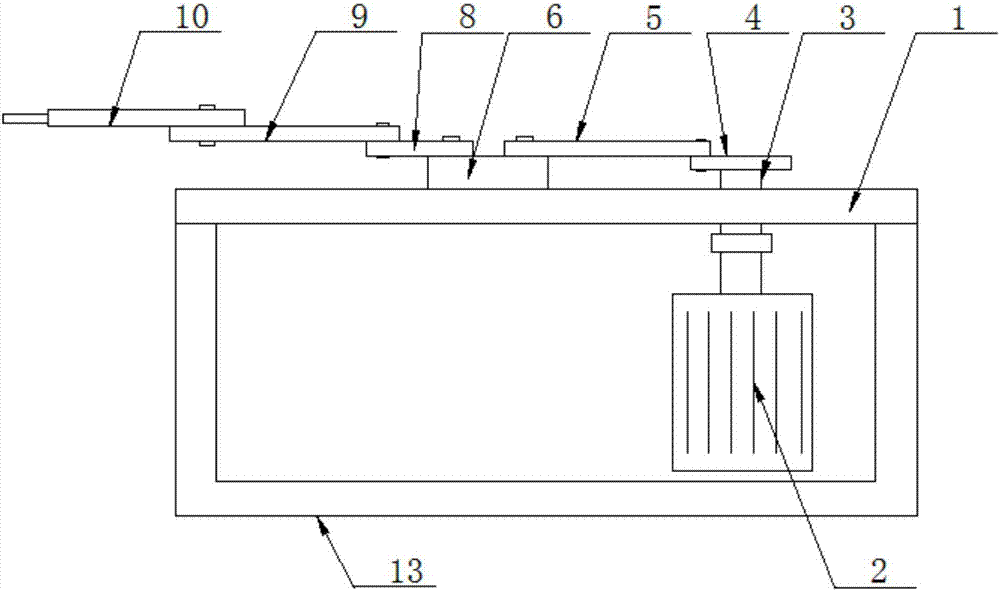
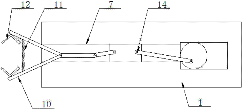
[0018] see as figure 1 —— figure 2 As shown, the specific embodiment adopts the following technical scheme: it includes a slide plate 1, a motor 2, an output shaft 3, a crank 4, a first connecting rod 5, a slider 6, a track 7, a second connecting rod 8, a rocking bar 9, Finger 10, spring 11; The bottom of described skateboard 1 is provided with motor 2, is connected with output shaft 3 on motor 2, is connected with crank 4 on output shaft 3, is connected with first connecting...
PUM
 Abstract
Description
Claims
Application Information