Laser cladding device

A technology of laser cladding and spectroscopic mirror, which is applied in the coating process and coating of metal materials, and can solve the problem of affecting the position accuracy of the reflective focusing mirror and reflector, affecting the modification or repair of the clad substrate, and affecting the precision of the device. To achieve the best cooling effect, ensure the modification or repair, and improve the service life

Active Publication Date: 2017-09-29
SUZHOU UNIV
View PDF9 Cites 5 Cited by
  • Summary
  • Abstract
  • Description
  • Claims
  • Application Information

AI Technical Summary

Problems solved by technology

However, the heat on the beam splitter and reflective focus mirror is often different, and the current optical path cooling system usually uses a water system to cool the beam splitter and reflective focus mirror, which cannot be controlled separately according to the different temperatures of the reflector and reflective focus mirror. It cools down to achieve different degrees of cooling, which leads to poor cooling effect of the device and affects the modification or repair of the cladding substrate
[0009] At the same time, since the water inlet and water outlet of the existing optical path cooling system are usually set inside the laser cladding device, when removing the nozzle of the laser cladding device, it is necessary to disassemble the nozzle and take it out to install it with the water inlet and water outlet. The pipes of the water supply system, such repeated disassembly and installation will affect the position accuracy of the reflective focusing mirror and reflector, thus affecting the precision of the device

Method used


Image

  • Laser cladding device
  • Laser cladding device
  • Laser cladding device

Examples


Embodiment Construction

[0032]The specific implementation manners of the present invention will be further described in detail below in conjunction with the accompanying drawings and embodiments. The following examples are used to illustrate the present invention, but are not intended to limit the scope of the present invention.

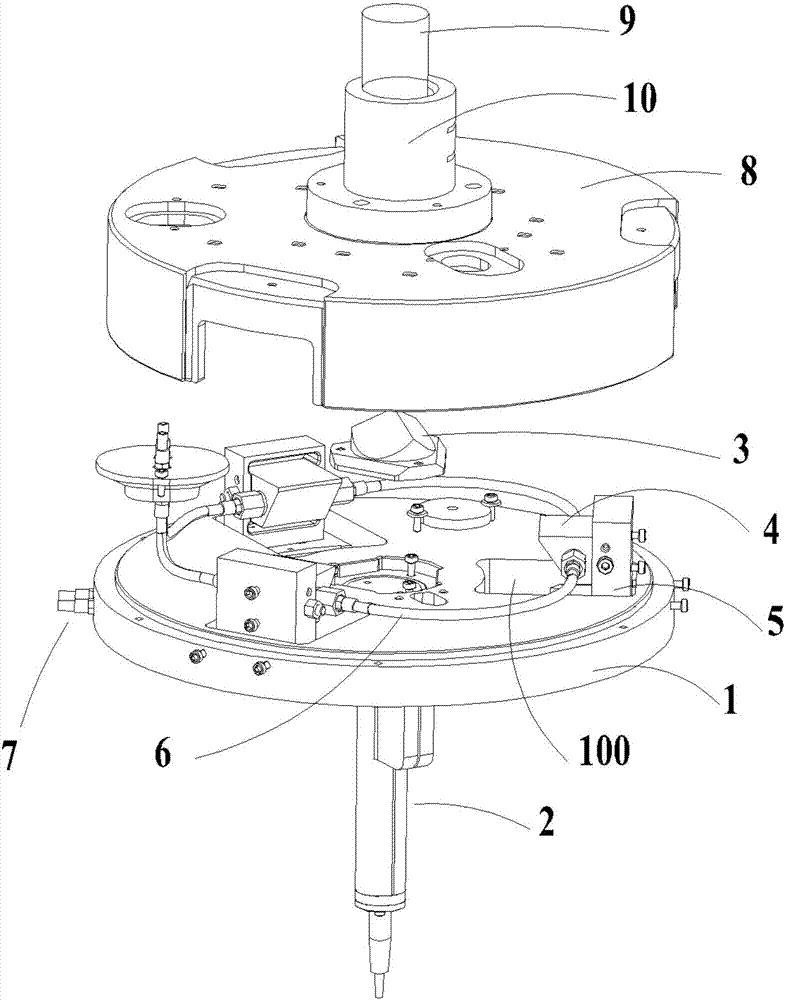
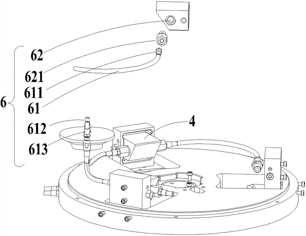
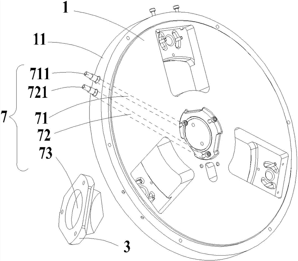
[0033] See figure 1 and Figure 9 , the laser cladding device of the present invention includes a support base 1 and a nozzle 2 located below the support base 1 . The support base 1 is a cylinder, the support base 1 has an upper surface 14, the upper surface 14 is provided with an adjustment bracket 5, and the upper surface 14 is concavely formed with a beam splitter groove for fixing the beam splitter 15. A bracket groove for fixing each of the adjustment brackets 5 and a light outlet 100 penetrating through the support base are formed in the concave. The support base 1 is provided with a beam splitter 3 and at least two reflective focusing mirrors 4, and the reflective...


PUM


Abstract

The invention relates to a laser cladding device. The laser cladding device comprises a supporting base and a nozzle which is located below the supporting base. The supporting base is provided with a spectroscope and at least two reflection focus lenses. The spectroscope receives an incident beam and reflects the incident beam into a reflection beam, and the reflection focus lenses receive the reflection beam and convert the reflection beam into focused beams. The supporting base is further provided with a first cooling system and a second cooling system, wherein the first cooling system is used for enabling a cooling medium to circularly flow so as to cool the reflection focus lenses, and the second cooling system is used for enabling the cooling medium to circularly flow so as to cool the spectroscope. The laser cladding device is provided with two independent water path systems, water or cooling liquid at different temperatures is input to the spectroscope and the reflection focus lenses according to the heat on the spectroscope and the heat on the reflection focus lenses, the purpose of respective cooling is achieved, a relatively-good cooling effect is achieved, the service life of the spectroscope and the reflection focus lenses is prolonged, thermal deformation of the focus lenses and the spectroscope is reduced, and the modification or repairing situation of a cladded base body is guaranteed.

Description

technical field [0001] The invention relates to a laser cladding device, which belongs to the field of laser processing. Background technique [0002] Laser cladding refers to placing the selected coating material on the surface of the substrate to be clad in different ways, and then irradiating it with laser to melt it and a thin layer on the surface of the substrate at the same time, and form a very low dilution after rapid solidification. The surface coating that forms a metallurgical combination with the substrate can significantly improve the wear resistance, corrosion resistance, heat resistance, oxidation resistance and electrical properties of the base surface, so as to achieve the purpose of surface modification or repair. Laser cladding can be roughly divided into two categories according to the supply method of cladding materials, namely preset laser cladding and synchronous laser cladding. Pre-set laser cladding is to pre-place the cladding material on the cladd...

Claims


Application Information

Patent Timeline
Patent Type & Authority Applications(China)
IPC IPC(8): C23C24/10
CPCC23C24/10Y02P10/25
Inventor 傅戈雁吉绍山刘凡石世宏鲁健
Owner SUZHOU UNIV
Why Eureka
Try Eureka