Inversion method of atmospheric refractivity profile

A technology of atmospheric refractivity and profile, applied in the direction of phase influence characteristic measurement, etc., can solve problems such as atmospheric refractivity, meteorological measuring instrument error, and high-precision ranging error compensation that are difficult to empirical formulas, and solve practical engineering problems Effect

Active Publication Date: 2017-09-29
XIDIAN UNIV +1
View PDF2 Cites 10 Cited by
  • Summary
  • Abstract
  • Description
  • Claims
  • Application Information

AI Technical Summary

Problems solved by technology

The above two methods both rely on the empirical formula of atmospheric refractivity and meteorological parameters. Although the empirical formula of atmospheric refractivity has been innovated and revised again and again since it was proposed by Barrell & Sears, it is difficult for the empirical formula to fully fit the atmospheric refractivity and meteorological parameters. It is also difficult for the meteorological parameter database to completely simulate the meteorological parameter profile of the measurement area. At the same time, there are certain errors in the meteorological measuring instruments, so the above methods cannot be used for high-precision distance measurement error compensation.

Method used


Image

  • Inversion method of atmospheric refractivity profile
  • Inversion method of atmospheric refractivity profile
  • Inversion method of atmospheric refractivity profile

Examples


Embodiment Construction

[0036] The following will clearly and completely describe the technical solutions of the embodiments of the present invention with reference to the accompanying drawings in the embodiments of the present invention. Obviously, the described embodiments are only some, not all, embodiments of the present invention. Based on the embodiments of the present invention, all other embodiments obtained by persons of ordinary skill in the art without making creative efforts belong to the protection scope of the present invention.

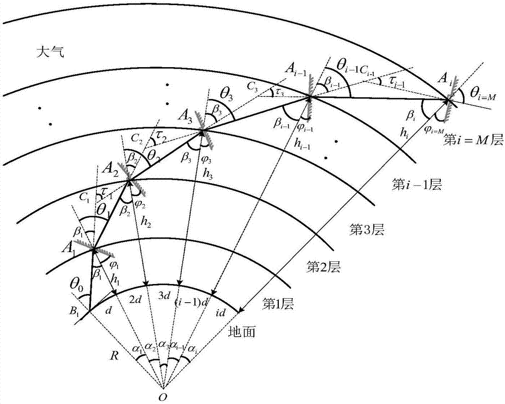
[0037] In the actual atmosphere, electromagnetic waves (light waves, radio waves) propagate along curves and broken lines. The atmospheric refractive index N or atmospheric refractive index n is a function of atmospheric temperature, humidity, and pressure. It changes irregularly with time and space, and is a random phenomenon. Processes, random field problems, are also common parameters to describe the electromagnetic properties of all media. In the applicati...


PUM

PropertyMeasurementUnit
heightaaaaaaaaaa
viewing angleaaaaaaaaaa

Abstract

The invention relates to an inversion method of the atmospheric refractivity profile. The method comprises the steps that an atmospheric layer is layered; beacon laser is emitted; air sounding equipment vertically ascends to the sounding height of each atmospheric sub layer; the deflection angle of a reflector when the reflector in the air sounding equipment intercepts and captures the beacon laser and returns the beacon laser to a laser receiver, and the received light intensity is maximum is measured; the geocentric angle of the reflector in each atmospheric sub layer and the incidence angle of the beacon laser in each atmospheric sub layer are calculated; the total refraction angle of each atmospheric sub layer and the gradient of the atmospheric refractivity along with the height change are calculated; a drawing is made by using the height as the X axis, the atmospheric refractivity as the Y axis, the atmospheric refractivity of each atmospheric sub layer as a starting point and the gradient of the atmospheric refractivity along with the height change as the slope at each section; the atmospheric refractivity profile is obtained. The inversion method disclosed by the method has the advantages that the atmospheric refractivity profile can be reversed in real time on the spot; technical support and theoretical support are provided for laser application to various engineering fields of satellite high-precision orbit determination, space high-precision measurement and the like which use precise phase information as a basis.

Description

technical field [0001] The invention belongs to the technical field of laser atmospheric application, and in particular relates to a method for inverting the atmospheric refractivity profile in real time and on the spot based on the cooperation of laser detection technology, precision instrument control technology and radio wave refraction theory. Background technique [0002] Lasers known as "the fastest knife", "the most accurate ruler", "the brightest light" and "singular light" have excellent characteristics such as good monochromaticity, strong coherence and good directionality, and are widely used It is used in communication, radar, ranging, remote sensing and other fields. Using laser as the carrier and relying on precise phase information, the satellite-ground link laser ranging technology can meet the requirements of millimeter-level ranging accuracy, such as the requirements of precise orbit determination of aviation aircraft and aircraft docking. [0003] The acc...

Claims


Application Information

Patent Timeline
Patent Type & Authority Applications(China)
IPC IPC(8): G01N21/43
CPCG01N21/43
Inventor 弓树宏侯牡玉吉登斌
Owner XIDIAN UNIV
Why Eureka
Try Eureka