Material drying system

A drying system and material technology, applied in the direction of using liquid separation agent, combination device, lighting and heating equipment, etc., can solve the problems of heat waste, increase production cost, limited heat exchange efficiency, etc., and achieve the elimination of PM2.5, flow rate The effect of lowering and volume reduction

Pending Publication Date: 2017-10-03
ZHEJIANG DEYAO ENERGY SAVING TECH CO LTD
View PDF14 Cites 0 Cited by
  • Summary
  • Abstract
  • Description
  • Claims
  • Application Information

AI Technical Summary

Problems solved by technology

[0004] However, when this kind of treatment equipment is used for tail gas treatment, the heat exchange process of the heat exchange device is that the exhaust gas overflows the excess heat and exchanges heat with the water in the heat exchange tube. Due to the limited heat exchange efficiency of this heat exchange method, the exhaust gas After the heat exchange by the heat exchange device, the residual temperature is still relatively high, so the heat of the exhaust gas higher than the atmospheric temperature is wasted, and the heat recovery rate is low
Moreover, the residual temperature of the exhaust gas is high, the molecular movement is violent, and the flow rate is relatively large. When passing through the washing and absorbing device and the spraying device, the water in the washing and absorbing device and the spraying device will also evaporate, resulting in the waste of this part of industrial water. Water sources also greatly increase production costs
In addition, when the residual temperature of the exhaust gas is high, the air molecules move violently and the flow velocity is large, and the fine dust and PM2.5 particles in the exhaust gas also move violently, which is not conducive to settlement and is not easy to be absorbed by spraying. exacerbated the smog
Therefore, this tail gas treatment process is very limited for water and heat recovery, and is not conducive to preventing smog

Method used


Image

  • Material drying system
  • Material drying system
  • Material drying system

Examples


Embodiment Construction

[0021] Embodiments of the present invention will be further described below in conjunction with the accompanying drawings.

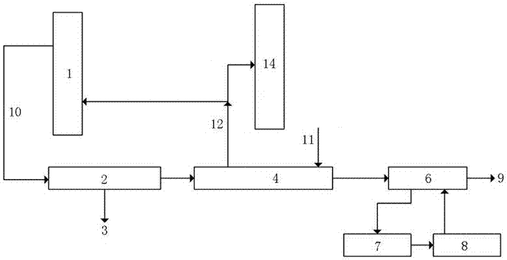
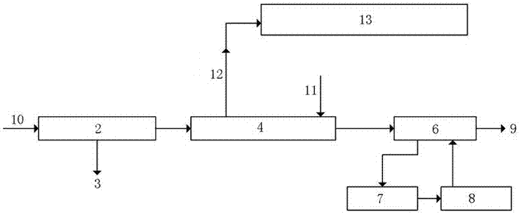
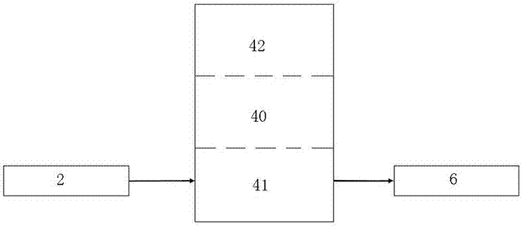
[0022] Embodiment one of the material drying system of the present invention, as figure 1 , 4 As shown, it includes a dryer 1, a dust removal device 2 for dedusting the introduced tail gas, and a heat pump system 4 for absorbing heat, cooling, condensing, and dehumidifying the tail gas after dust removal, and for heat pump The tail gas treated in system 4 is subjected to secondary cooling and dust removal treatment of wet dust removal device 6, the air outlet of dust removal device 2 is connected to the air inlet of heat-absorbing unit of heat pump system 4, and the air outlet of heat-absorbing unit of heat pump system 4 is connected to wet dust removal device 6, the wet dedusting device 6 is connected with a sedimentation tank 7 for recycling dedusting water, the sedimentation tank 7 is connected with a clear water tank 8, and the clear water tank 8 is...


PUM


Abstract

The invention provides a material drying system. The material drying system comprises a drying part and an exhaust treatment part, wherein the exhaust treatment part comprises a dedusting device for dedusting treatment on imported exhaust, at least one thermal pump system for heat absorption, cooling, condensing and dehumidifying of exhaust subjected to dedusting treatment, and a wet dust collection device for dust treatment on the exhaust treated by the thermal pump system, an air outlet of the dedusting device is connected with a heat absorption unit air inlet of the thermal pump system, and a heat absorption unit air outlet of the thermal pump system is communicated with an air inlet of the wet dust collection device. The exhaust in the material drying system is dedusted by the dedusting device for the first time and then is introduced into a heat absorption unit of the thermal pump system, a large quantity of heat in the exhaust is absorbed in the heat absorption unit of the thermal pump system, causing the exhaust temperature to reduce substantially to 55 DEG C or below, as a result, dedusting water is prevented from being evaporated in a wet dust collection stage, dust in the exhaust falls down better and is absorbed by wet dust collection water, so that smog is eliminated.

Description

technical field [0001] The invention relates to industrial tail gas treatment, in particular to a material drying system. Background technique [0002] In recent years, smog has become serious in some areas, and environmental problems have risen to a new height, which has had a serious negative impact on the national economy and people's livelihood. Energy conservation, emission reduction, and eradication of smog have become important livelihood projects and important measures advocated by the state and enterprises. With the development of industry, the emission of industrial tail gas is more serious. Usually, most of the industrial tail gas is directly discharged after simple treatment, which is far from meeting the environmental protection requirements. Common industrial exhaust gas includes boiler exhaust gas, material preheating exhaust gas, drying exhaust gas, etc. The discharged exhaust gas not only has a high temperature, which can reach hundreds of degrees, but also ...

Claims


Application Information

Patent Timeline
Patent Type & Authority Applications(China)
IPC IPC(8): B01D50/00B01D53/00B01D53/26B01D47/06F25B30/06
CPCB01D47/06B01D50/00B01D53/002B01D53/26F25B30/06B01D2258/02B01D2257/80B01D50/40B01D50/60
Inventor 唐德顺
Owner ZHEJIANG DEYAO ENERGY SAVING TECH CO LTD
Why Eureka
Try Eureka