
High-efficiency anti-clogging cyclone combined jet aeration device

A jet aeration and combined technology, applied in water aeration, sustainable biological treatment, water/sludge/sewage treatment, etc., can solve the problems of easy aging and damage of aerator diaphragm, aerator fouling and clogging, Difficult repair and maintenance, etc., to prolong oxygen transfer and diffusion time, improve mass transfer rate and transfer rate, and high oxygenation energy rate

Pending Publication Date: 2017-10-03
宜兴市荣盛达环保有限公司
View PDF5 Cites 3 Cited by
  • Summary
  • Abstract
  • Description
  • Claims
  • Application Information

AI Technical Summary

Problems solved by technology

[0003] Disadvantages of traditional blower aerators: 1. Since the microporous aerator diaphragm is made of rubber, in order to ensure the service life of the diaphragm, the operating wind pressure of the blower needs to be maintained at a low value, so the operation of the biochemical pool is designed The liquid level should not be too deep; 2. In order to ensure the efficient oxygenation of the microporous aerator, the sludge concentration in the biochemical tank should not be too high, which will indirectly affect the treatment effect of the biochemical system and the impact load resistance; 3. When the hardness of the sewage is too high 4. The diaphragm of the aerator is easily aged and damaged under long-term pressure, and the service life is short. It is difficult and expensive to repair and maintain the equipment in the later stage.

Method used


Image

  • High-efficiency anti-clogging cyclone combined jet aeration device
  • High-efficiency anti-clogging cyclone combined jet aeration device

Examples


Embodiment Construction

[0015] In order to make the objectives, technical solutions and advantages of the present invention clearer, the technical solutions in the embodiments of the present invention will be described in more detail below in conjunction with the drawings in the embodiments of the present invention. In the drawings, the same or similar reference numerals denote the same or similar elements or elements having the same or similar functions throughout. The described embodiments are some, but not all, embodiments of the invention. The embodiments described below by referring to the figures are exemplary and are intended to explain the present invention and should not be construed as limiting the present invention. Based on the embodiments of the present invention, all other embodiments obtained by persons of ordinary skill in the art without creative efforts fall within the protection scope of the present invention. Embodiments of the present invention will be described in detail below ...


PUM

PropertyMeasurementUnit
diameteraaaaaaaaaa
diameteraaaaaaaaaa
diameteraaaaaaaaaa

Abstract

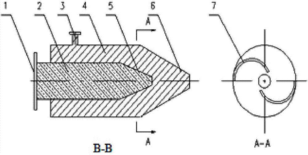
The invention discloses a high-efficiency anti-clogging cyclone combined jet aeration device. The jet aeration device comprises a gaseous phase pipe, a liquid phase pipe, a water inlet end, a gas inlet end, a water chamber, a gas chamber, hydraulic ejectors, gas-liquid ejectors and a gas-liquid cyclone structure, wherein multiple groups of concentric hydraulic ejectors and gas-liquid ejectors are arranged on the side of the gaseous phase pipe and the side of the liquid phase pipe; the liquid phase pipe is connected with the water inlet end; the water inlet end is connected with the water chamber; the hydraulic ejectors are arranged at the end part of the water chamber; the gaseous phase pipe is connected with the gas inlet end; the gas inlet end is arranged on the side of the gas chamber; the gas-liquid ejectors are arranged at the end part of the gas chamber; the water chamber and the hydraulic ejectors are coaxial and are arranged in the gas chamber and the gas-liquid ejectors along the same direction. According to the high-efficiency anti-clogging cyclone combined jet aeration device disclosed by the invention, tapers and ejection orifices of the hydraulic ejectors and the gas-liquid ejectors are optimized, gas-liquid rapid mixed cutting and spiral jetting in the gas chamber are realized, the oxygenation diffusion capacity of jet flows is improved, and double functions of pushing flow and diffusion are realized.

Description

technical field [0001] The invention relates to the technical field of jet aeration for sewage treatment, in particular to a high-efficiency anti-clogging swirling combined jet aeration device suitable for industrial or urban sewage treatment. Background technique [0002] At present, conventional aeration devices in sewage biochemical treatment systems are divided into two types: blast aerators and mechanical aerators. Mechanical aerators are divided into: rotating disc aerators, rotating brush aerators, inverted umbrella impeller aerators; blast aerators are divided into: microporous aerators, jet aerators, underwater aerators device. [0003] Disadvantages of traditional blower aerators: 1. Since the microporous aerator diaphragm is made of rubber, in order to ensure the service life of the diaphragm, the operating wind pressure of the blower needs to be maintained at a low value, so the operation of the biochemical pool is designed The liquid level should not be too de...

Claims


Application Information

Patent Timeline
Patent Type & Authority Applications(China)
IPC IPC(8): C02F7/00C02F3/02
CPCC02F3/02C02F7/00Y02W10/10
Inventor 丁海荣王庆芬毛旭强殷浩范公明岳振平
Owner 宜兴市荣盛达环保有限公司
Learn More