Adsorbed fabric singeing equipment

An adsorption and fabric technology, applied in the field of textile production, can solve the problems that the fiber is not cleaned, the erection effect cannot be controlled, and cannot be realized, and achieves excellent singeing effect, improved fiber treatment effect, and high-efficiency fiber hair removal. Effect

Inactive Publication Date: 2017-10-03
长兴天赫纺织科技有限公司
View PDF1 Cites 5 Cited by
  • Summary
  • Abstract
  • Description
  • Claims
  • Application Information

AI Technical Summary

Problems solved by technology

[0004] The above-mentioned technical scheme uses static electricity to make the fibers on the surface of the fabric stand up and then performs singeing treatment. However, it uses static electricity to realize the erection of the fibers, and the erection effect cannot be controlled. It cannot be realized in the case of knotting or interlaced winding between fibers. , which does not remove the fiber drop after singeing

Method used


Image

  • Adsorbed fabric singeing equipment
  • Adsorbed fabric singeing equipment
  • Adsorbed fabric singeing equipment

Examples


Embodiment 1

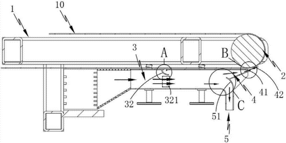
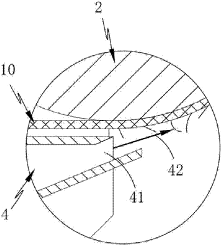
[0040] Such as figure 1 , 2 As shown in and 3, an adsorption-type cloth singeing device includes a support 1 and a cloth guide roller 2 that is rotatably mounted on the support 1 for conducting the cloth 10, and also includes:

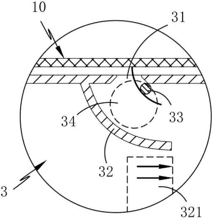
[0041] The airflow channel 3, the airflow channel 3 is located below the cloth 10, the airflow channel 3 includes an adsorption hole 31 set on its top, a baffle plate 32 fixedly arranged on one side of the adsorption hole 31, and a baffle plate 32 arranged on the adsorption hole 31 The heating wire 33 on the other side forms an airflow acceleration zone 321 between the baffle plate 32 and the opposite airflow passage wall, and the airflow flows along the airflow passage 3 and is formed at the adsorption hole 31 through the airflow acceleration zone 321 Negative pressure zone 34; during the transmission process of the cloth 10, the cloth 10 passes through the adsorption hole 31 continuously, and the fibers on the surface of the cloth 10 pass through th...

Embodiment 2

[0048] Such as Figure 5 and 6 As shown, the components that are the same as or corresponding to those in the first embodiment are marked with the corresponding reference numerals in the first embodiment. For the sake of simplicity, only the differences from the first embodiment will be described below. The difference between the second embodiment and the first embodiment is that it also includes a combing assembly 6 arranged on the support 1 and in contact with the upper surface of the cloth 10. The combing assembly 6 includes:

[0049] Combing roller brush 61, described carding roller brush 61 is rotated and arranged directly above the cloth 10, and its outer peripheral surface is provided with a number of combing teeth 611 for fluffing the surface fibers of the cloth 10; the combing teeth 611 are convexly arranged;

[0050] The transmission part 62, the carding roller brush 61 and the cloth guide roller 2 are connected through the transmission part 62, and between the spee...

Embodiment 3

[0055] Such as Figure 9 As shown, the same or corresponding components as in Embodiment 1 and Embodiment 2 adopt the corresponding reference numerals as in Embodiment 1 and Embodiment 2. For the sake of simplicity, only the differences from Embodiment 1 and Embodiment 2 are described below. point. The difference between this embodiment three and embodiment one and embodiment two is that: at least two adsorption holes 31 are arranged on the top of the airflow channel 3 along the conveying direction of the cloth 10; Adsorption holes 31 carry out fiber adsorption, and the amount of gas sucked into the fibers is limited, so the hair removal rate of the cloth 10 will decrease. However, a plurality of adsorption holes 31 are adopted, and the fibers pass through the plurality of adsorption holes 31 to improve the hair removal rate of the cloth 10. Simultaneously, when the fiber has reached the requirement of depilation, the adsorption hole 31 carries out a certain amount of adsorpt...


PUM


Abstract

The invention relates to an adsorption-type cloth singeing equipment, which includes a bracket and a cloth guide roller, and also includes an airflow channel, a blowing channel and a collection channel. The baffle plate fixed on one side of the adsorption hole and the heating wire arranged on one side of the adsorption hole form an airflow acceleration area between the baffle plate and the opposite airflow channel wall, and the airflow flows along the airflow channel, passing through the airflow acceleration area and reaching the adsorption hole A negative pressure area is formed at the position; the blowing channel is located below the cloth guide roller and communicated with the air flow channel, and the gas passing through the air flow channel forms a gas curtain at the air outlet of the blowing channel, and the gas curtain and the guide cloth The rollers are arranged tangentially; the collection channel is connected to the air flow channel and the collection channel is located below the blowing channel, and a deflector is set between the blowing channel and the collecting channel, and the fibers at the bottom of the air flow channel are guided by the air flow Plate guide for debris collection.

Description

technical field [0001] The invention relates to the field of textile production, in particular to an adsorption type cloth singeing equipment. Background technique [0002] The process of burning yarn or fabric quickly through a flame or rubbing it over a hot metal surface to burn off the fuzz on the surface. The fiber will produce a lot of fuzz on the surface of the yarn and fabric after textile processing, which will affect the process effect of dyeing and finishing. When the fabric is singed, after the fabric is processed, conveyed or transported, the textured fibers on the surface are often in an irregular lodging state after being squeezed, which will lead to uneven singeing on the surface of the fabric or some fibers that need to be burnt because they are close to the fabric. The surface is not burned, which greatly affects the physical properties and aesthetics of the fabric. [0003] An electrostatic singeing device disclosed in Chinese invention patent application...

Claims


Application Information

Patent Timeline
Patent Type & Authority Applications(China)
IPC IPC(8): D06C9/04D06C11/00
CPCD06C9/04D06C11/00
Inventor 顾钰琛
Owner 长兴天赫纺织科技有限公司
Why Eureka
Try Eureka