Eureka AIR delivers breakthrough ideas for toughest innovation challenges, trusted by R&D personnel around the world.
Hydraulic system and control method of heavy-duty forging equipment with controllable feed speed
What is Al technical title?
Al technical title is built by PatSnap Al team. It summarizes the technical point description of the patent document.
A technology of forging equipment and feed speed, applied in the field of forging, can solve the problems of large gap in international standards, large equipment vibration, poor practicability, etc., and achieve the effects of good sealing, large flow capacity, and sensitive action
Active Publication Date: 2019-01-01
WUHAN UNIV OF TECH
View PDF10 Cites 2 Cited by
Summary
Abstract
Description
Claims
Application Information
AI Technical Summary
This helps you quickly interpret patents by identifying the three key elements:
Problems solved by technology
Method used
Benefits of technology
Problems solved by technology
my country's forging industry has nearly 3,000 forging hydraulic presses of different tonnages such as 800-18500T. It has an international advanced level in forging capacity, but there is a large gap between the forging frequency and the international level, especially for heavy-duty forging equipment. The rapid forging frequency of domestic forging hydraulic presses is generally 45 times / min, while that of foreign forging hydraulic presses is generally 90 times / min, and domestic hydraulic forging machines vibrate a lot under fast forging conditions, which is practical bad sex
Method used
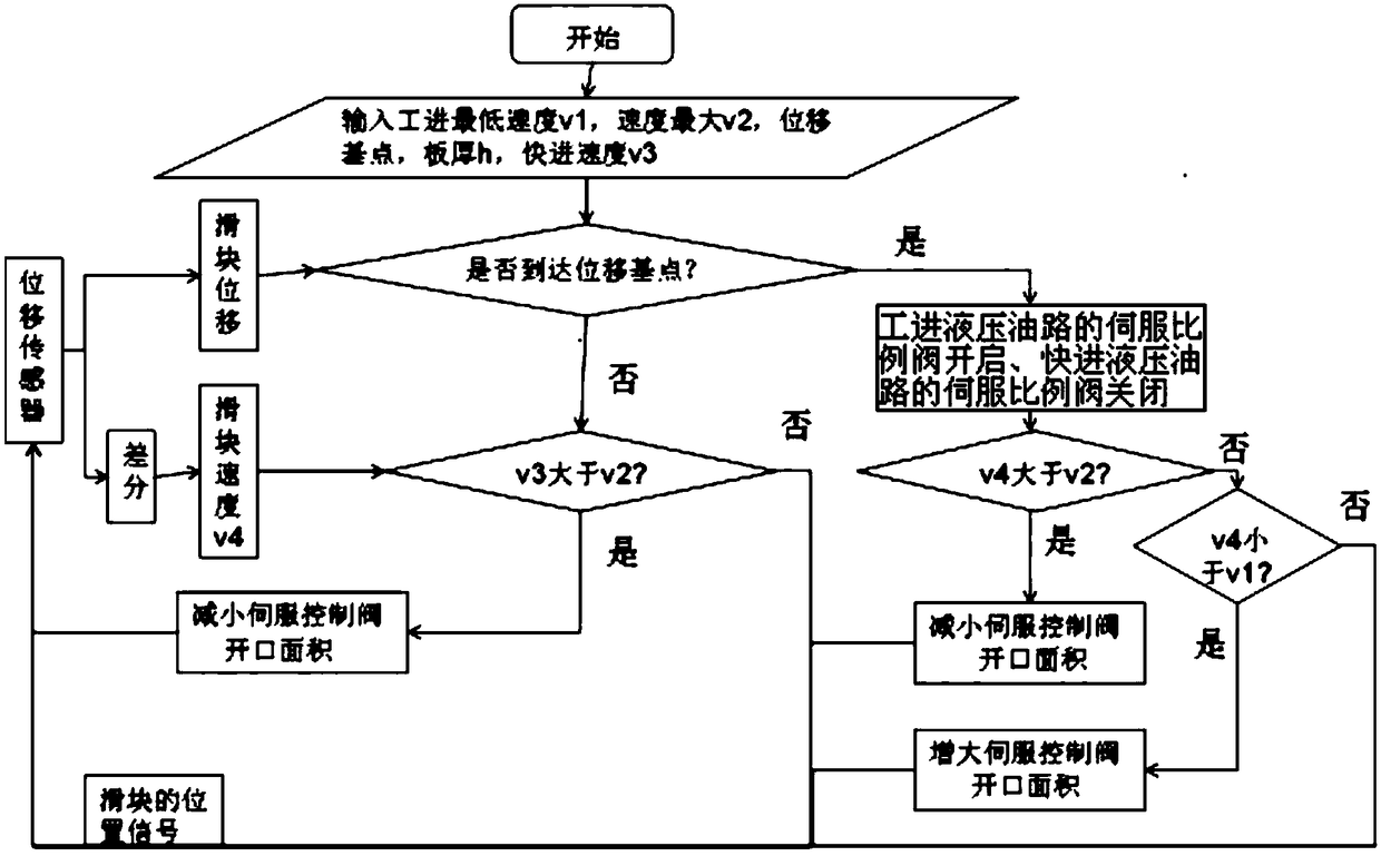
Image
Click on the blue label to locate the original text in one second.
Reading with bidirectional positioning of images and text.
Examples
Embodiment Construction
[0020] The present invention will be further described below in conjunction with the accompanying drawings and embodiments.
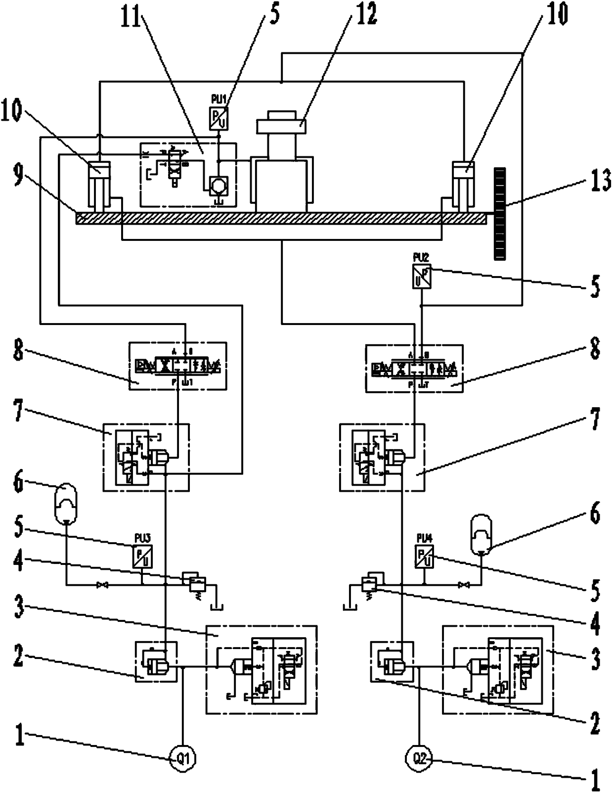
[0021] Such as figure 1 As shown, a hydraulic system for heavy-duty forging equipment with controllable feed speed, including a slider 9, a displacement sensor 13 arranged on the slider 9, and a piston rod connected to the slider 9 and arranged symmetrically on the slider 9 The double-acting fast-forward cylinder 10 (the double-acting fast-forward cylinder 10 has a small bore and a long working stroke, and is symmetrically arranged on the four corners of the slider 9), the fast-forward hydraulic oil circuit, the piston rod and the slider 9 are connected and The single-acting working cylinder 12 located in the middle of the slider 9 (the single-acting working cylinder 12 has a large bore and short effective working stroke), the working hydraulic oil circuit, the human-machine interface and the industrial computer; the fast-forward hydraulic oil circuit a...
PUM
Abstract
The invention relates to a heavy-load forging and pressing equipment hydraulic system with controllable feeding speed, and a control method. The heavy-load forging and pressing equipment hydraulic system comprises a sliding block, a displacement sensor, a double-acting fast feeding cylinder, a fast feeding hydraulic oil way, a single-acting working-feeding cylinder, a working-feeding hydraulic oil way, a human-computer interface and an industrial personal computer. The fast feeding hydraulic oil way and the working-feeding hydraulic oil way each comprise an oil source, a one-way cartridge valve set, a direction control cartridge valve set, a servo proportional valve, a pressure cartridge valve set, an oil pressure sensor and an energy accumulator. The working-feeding hydraulic oil way further comprises a liquid charging valve set. The industrial personal computer is connected with the human-computer interface, the one-way cartridge valve set, the pressure cartridge valve set, the oil pressure sensor, the direction control cartridge valve set, the servo proportional valve, the liquid charging valve set and the displacement sensor. According to the heavy-load forging and pressing equipment hydraulic system with the controllable feeding speed, and the control method, production efficiency is improved, the needs for flow are relatively small, machining requirements of various forge pieces with large sizes and complex shape sizes can be met, energy is saved, efficiency is improved, and high precision of motion of forging and pressing equipment is ensured.
Description
technical field [0001] The invention belongs to the field of forging, and in particular relates to a hydraulic system and a control method of heavy-duty forging equipment with controllable feed speed. technical background [0002] The use of impact force or pressure to deform metal between anvils or forging dies to obtain forgings of desired shape and size is called forging. The forging press is a special equipment for forging and forming. Among them, the forging hydraulic press has multiple functions such as fast forging, general forging, slow drop, and pressure holding. It is a high-performance pressure forging equipment for various forging process requirements. my country's forging industry has nearly 3,000 forging hydraulic presses of different tonnages such as 800-18500T. It has an international advanced level in forging capacity, but there is a large gap between the forging frequency and the international level, especially for heavy-duty forging equipment. The rapid f...
Claims
Application Information
Patent Timeline
Application Date:The date an application was filed.
Publication Date:The date a patent or application was officially published.
First Publication Date:The earliest publication date of a patent with the same application number.
Issue Date:Publication date of the patent grant document.
PCT Entry Date:The Entry date of PCT National Phase.
Estimated Expiry Date:The statutory expiry date of a patent right according to the Patent Law, and it is the longest term of protection that the patent right can achieve without the termination of the patent right due to other reasons(Term extension factor has been taken into account ).
Invalid Date:Actual expiry date is based on effective date or publication date of legal transaction data of invalid patent.