Flow sensor for pulmonary function test, pulmonary function tester and application

A flow sensor and lung function technology, applied in the field of flow sensors, can solve the problems of increasing the production process, the complexity of after-sales maintenance, increasing the complexity of instruments, reducing reliability, etc. Correction, the effect of low manufacturing cost

Pending Publication Date: 2017-10-13
TAIZHOU E LINKCARE MEDITECH CO LTD
View PDF8 Cites 4 Cited by
  • Summary
  • Abstract
  • Description
  • Claims
  • Application Information

AI Technical Summary

Problems solved by technology

However, since the inspiratory flow rate of the human body is much smaller than the exhalation flow rate, two sets of pressure-taking ports are used to detect the expiratory and inspiratory flow rates at the same time, and the sensitivity of inspiratory detection is not enough. The sensor 1008 includes a high-range differential pressure sensor and a low-range differential pressure sensor. The high-range differential pressure sensor is used to detect the expiratory flow, and the low-r...

Method used


Image

  • Flow sensor for pulmonary function test, pulmonary function tester and application
  • Flow sensor for pulmonary function test, pulmonary function tester and application
  • Flow sensor for pulmonary function test, pulmonary function tester and application

Examples


Embodiment 1

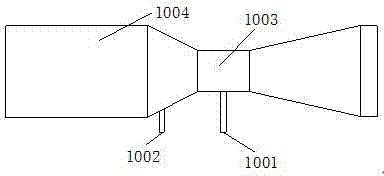
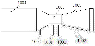
[0060] The experimental group is the flow sensor according to the present invention, the diameter of the exhalation air intake part is 27mm, the cone angle of the first cone is 40 degrees, the throat diameter is 12mm, and the cone angle of the second cone is 25.4 degrees, The suction inlet diameter is 27mm. The distance between the first high pressure tap and the low pressure tap is 20mm, and the distance between the second high pressure tap and the low pressure tap is 25mm.

[0061] The control group is a dual-hole flow sensor of the prior art, the diameter of the expiratory inlet part is 27 mm, the cone angle of the first cone is 40 degrees, the diameter of the throat part is 12 mm, and the cone angle of the second cone is 25.4 degrees , The diameter of the suction inlet is 27mm. The distance between the first high pressure tap and the low pressure tap is 20mm.

[0062] The flow sensor of the experimental group and the flow sensor of the control group were compared with th...

Embodiment 2

[0069] Measure the maximum pressure difference of the flow sensor of the embodiment 1 experimental group, the expiratory flow maximum range is 900L / min, and the corresponding pressure difference is 10kPa when the maximum flow; the inspiratory flow maximum range is 600L / min, and the corresponding pressure difference is 10kPa when the maximum flow. Therefore, the first differential pressure sensor and the second differential pressure sensor can use differential pressure sensors with the same range. The two sensors were calibrated by experimentally testing flow and differential pressure data (see Table 3). For specific calibration, connect two differential pressure sensors in parallel and apply the same differential pressure, and take two differential pressure points of 1kPa and 5kPa for linear calibration.

[0070] table 3

[0071] Expiratory flow value (L / min)


PUM


Abstract

The invention provides a flow sensor for pulmonary function test, an application of the flow sensor to a pulmonary function tester and a pulmonary function testing method. The flow sensor is of a hollow tube structure and mainly formed by sequentially connecting an expiratory air inlet portion, a first cone, a throat and a second cone, a low-pressure pressure tap is formed in the tube wall of the throat, and a first high-pressure pressure tap and a second high-pressure pressure tap are formed in tube walls on two sides of the hollow tube structure except for the throat. The flow sensor and the pulmonary function tester can test bidirectional flow of expiration and inspiration and are compact in structure, convenient to calibrate and correct and simple in after-sales maintenance, and miniaturization of the pulmonary function tester is facilitated.

Description

technical field [0001] The invention relates to the field of medical devices, in particular to a flow sensor for lung function measurement, a lung function tester, an application and a measurement method thereof. Background technique [0002] The functions of various organs of the human body can only work normally when there is sufficient oxygen supply. The oxygen supply of the human body is obtained entirely by the respiration of the lungs. During the respiration process, the lungs take in oxygen and discharge the metabolite carbon dioxide. Pulmonary function measurement can be used to judge the respiratory function of the tester, and it has practical clinical significance in identifying the type of airway obstruction and evaluating lung function before thoracoabdominal surgery. [0003] With the advancement of technology, the lung function tester has gradually developed from the traditional buoy type and rotary type to an easy-to-carry electronic tester. In this type of ...

Claims


Application Information

Patent Timeline
IPC IPC(8): A61B5/087
CPCA61B5/087
Inventor 胡锡江方俊标陈志敏刘金玲王天星
Owner TAIZHOU E LINKCARE MEDITECH CO LTD
Why Eureka
Try Eureka