
Verification method, device, electronic equipment and storage medium for logic circuit design

A technology of logic circuits and verification methods, applied in computing, electrical digital data processing, instruments, etc., can solve problems such as difficult debugging, complex algorithm models, and low operating efficiency, achieve good scalability, improve verification efficiency, and avoid coding work Effect

Active Publication Date: 2018-11-02
SHENZHEN INTELLIFUSION TECHNOLOGIES CO LTD
View PDF7 Cites 0 Cited by
  • Summary
  • Abstract
  • Description
  • Claims
  • Application Information

AI Technical Summary

Problems solved by technology

[0003] At present, many algorithm models are complex, such as artificial intelligence algorithms (Artificial Intelligence, AI), and contain a large number of matrix operations
In the verification of the logic circuit code of this algorithm, if the algorithm involving a large number of matrix operations is implemented with an emulator, more cycles need to be used, the operating efficiency is low, and debugging is difficult
One solution is to use the direct programming interface (Direct Programming Interface) to call the reference model (such as the algorithm model written in C language). Since the code language of the simulator is different from the code language of the reference model, the simulator cannot directly Reading the code of the reference model has caused certain difficulties for debugging. For example, the SystemVerilog simulator cannot directly read the C code

Method used


Image

  • Verification method, device, electronic equipment and storage medium for logic circuit design
  • Verification method, device, electronic equipment and storage medium for logic circuit design
  • Verification method, device, electronic equipment and storage medium for logic circuit design

Examples


Embodiment Construction

[0045]The following will clearly and completely describe the technical solutions in the embodiments of the present invention with reference to the accompanying drawings in the embodiments of the present invention. Obviously, the described embodiments are only some, not all, embodiments of the present invention. Based on the embodiments of the present invention, all other embodiments obtained by persons of ordinary skill in the art without making creative efforts belong to the protection scope of the present invention.

[0046] In order to make the above objects, features and advantages of the present invention more comprehensible, the present invention will be further described in detail below in conjunction with the accompanying drawings and specific embodiments.

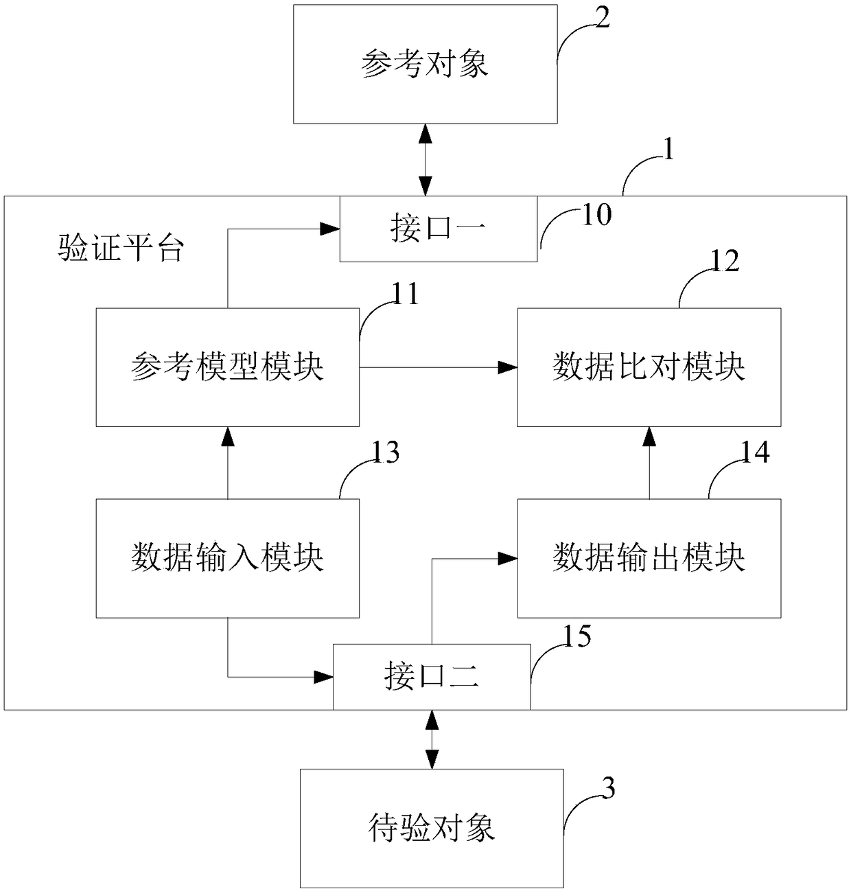
[0047] Such as figure 1 as shown, figure 1 It is a system architecture diagram of a preferred embodiment of the verification method for realizing logic circuit design of the present invention. In this preferred e...


PUM


Abstract

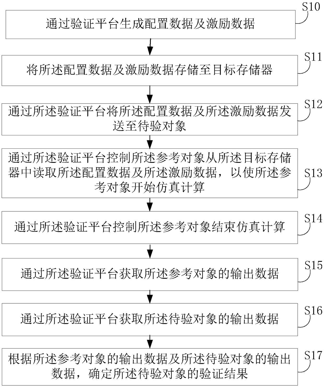
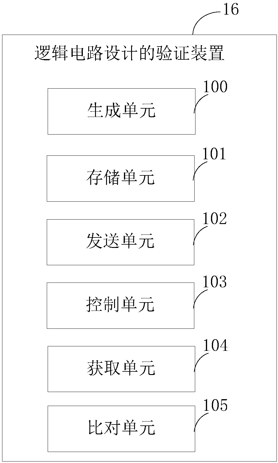
The invention provides a method for verifying a logic circuit design. The method comprises the following steps: generating configuration data and stimulation data through a verifying platform; storing the configuration data and the stimulation data into a target memory; transmitting the configuration data and the stimulation data to an object to be verified through the verifying platform; controlling a reference object to read the configuration data and the stimulation data from the target memory through the verifying platform so that the reference object begins to carry out simulation calculation, wherein the object to be verified is a logic circuit code which implements an algorithm by using a first language, and the reference object is a code for implementing the same algorithm by using a second language; controlling the reference object to finish simulation calculation through the verifying platform; acquiring output data of the reference object by the verifying platform; acquiring output data of the object to be verified through the verifying platform; and determining a verified result of the object to be verified according to the output data of the reference object and the object to be verified. The invention further provides a device for verifying the logic circuit design. The purpose of accurately verifying the object to be verified is achieved.

Description

technical field [0001] The present invention relates to the technical field of chip design, in particular to a logic circuit design verification method, device, electronic equipment and storage medium. Background technique [0002] As integrated circuits become more and more complex, the logic circuit codes written by digital IC design engineers through SystemVerilog, that is, Design Under Test (DUT), are also becoming more and more complex. How to ensure the correctness of logic circuit codes is becoming more and more important. . The work of digital IC verification engineers is mainly to write test programs based on Electronics Design Automation (EDA) software to verify the functions of logic codes. The current mainstream test program is based on the SystemVerilog language, which is a superset of Verilog and has object-oriented functions, which can easily construct higher-level abstraction programs. [0003] At present, many algorithm models are complex, such as artifici...

Claims


Application Information

Patent Timeline
Patent Type & Authority Patents(China)
IPC IPC(8): G06F17/50
CPCG06F30/398
Inventor 韦国恒田守政
Owner SHENZHEN INTELLIFUSION TECHNOLOGIES CO LTD
Learn More