Preparation method of carbon fiber waveguide

A technology of carbon fiber and carbon fiber sheet, which is applied in the field of integrated preparation of carbon fiber waveguide with metal coating, can solve the problems of peeling of the metal layer, affecting the continuity of the coating, and the difficulty of effectively preparing polymer transfer films, etc., so as to reduce manufacturing costs, copper Foil Layer Intact Effect

Active Publication Date: 2017-10-17
CHINA ELECTRONIC TECH GRP CORP NO 38 RES INST
View PDF5 Cites 5 Cited by
  • Summary
  • Abstract
  • Description
  • Claims
  • Application Information

AI Technical Summary

Problems solved by technology

The commonly used methods for preparing the metal layer of the composite material waveguide cavity are: electroless plating method, which is to deposit a layer of metal layer on the surface of the waveguide cavity by chemical plating after the carbon fiber waveguide is formed. The disadvantage of this method is that the carbon fiber The types of composite materials have certain selectivity, some materials are easy to be plated on the surface and some are not suitable for plating, and due to the complexity inside the cavity, the continuity of the coating cannot be guaranteed
Another method is the metal layer mandrel transfer method. In this method, the upper metal layer is prepared by electroplating on the mandrel, and then the carbon fiber composite material is for...

Method used


Image

  • Preparation method of carbon fiber waveguide
  • Preparation method of carbon fiber waveguide
  • Preparation method of carbon fiber waveguide

Examples


Embodiment 1

[0035] The steps to make a carbon fiber waveguide are as follows:

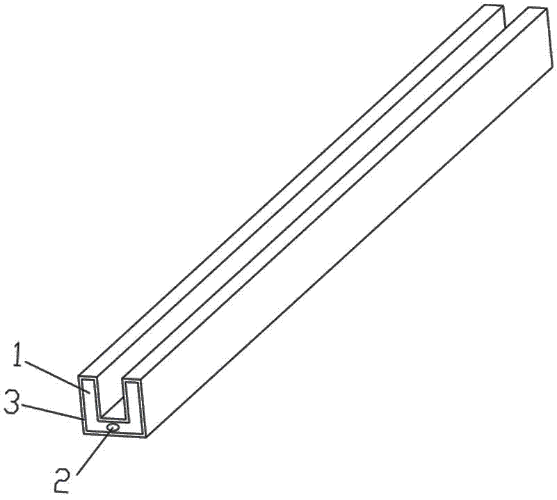
[0036] (1) Make the core mold of the waveguide that is easy to release the mold according to the conventional method

[0037] see figure 1 , according to the structure of the waveguide cavity, an easy-to-detach core mode is designed. The core mold 1 is made of steel material, which meets the rigidity and strength requirements during forming and demoulding. The surface roughness of the core mold 1 is not higher than 1.6, meeting the smoothness requirements of the waveguide cavity. The end of the mandrel 1 is designed with a demoulding screw hole 2 that is installed in cooperation with the demoulding screw. In order to facilitate matching with the demoulding auxiliary tooling, the length of the core mold 1 is 20mm longer than the actual waveguide size.

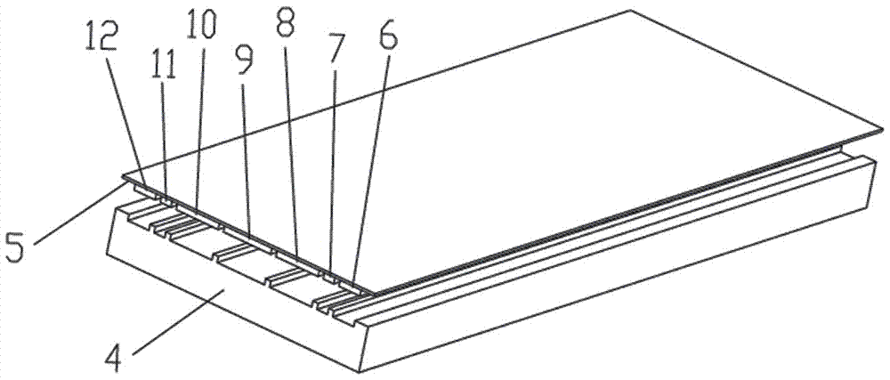
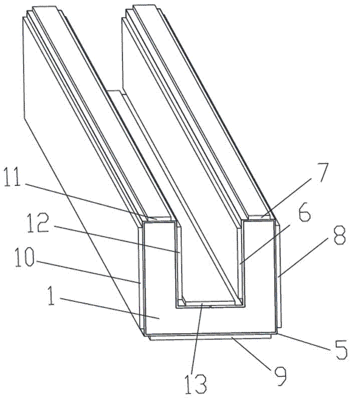
[0038] (2) Make an assembly of carbon fiber sheet and copper foil

[0039] according to figure 1 The length and cross-sectional dimensions of the carbon f...


PUM

PropertyMeasurementUnit
Thicknessaaaaaaaaaa
Thicknessaaaaaaaaaa

Abstract

The invention relates to a preparation method of a carbon fiber waveguide. The preparation method comprises the following operation steps that (1) a waveguide core mould easy to demould is manufactured according to a conventional method; (2) eight lath-shaped carbon fiber sheets are manufactured according to the shape of the channel-steel-shaped waveguide and pasted on a copper foil in sequence, and thus a composite piece of the carbon fiber sheets and the copper foil is obtained; (3) one side of the copper coil of the composite piece is wound on the waveguide core mould in a wrapping mode according to the design requirement, gaps are filled with carbon fibers, a blank is obtained after curing, the carbon fibers are laid and pasted on the blank, and a preformed piece is obtained after curing; and (4) the preformed piece is demoulded through a demoulding auxiliary tool in a mechanical traction mode, and thus the carbon fiber waveguide with an inner cavity being provide with the continuous and reliable copper foil is obtained. The preparation method has the advantages that a copper foil layer is complete, uniform and continuous, the effects of the metal layer preparation processes of electroplating, spraying and the like are avoided, the waveguide core mould can be reused, and the method is particularly suitable for preparation of the composite material waveguide with a complex cavity structure.

Description

technical field [0001] The invention belongs to the technical field of radar waveguide antenna manufacture, and in particular relates to an integrated preparation technology of a metal-coated carbon fiber waveguide. Background technique [0002] The waveguide antenna is an important structural form of the radar antenna, and it is generally used in the field of spaceborne radar. Due to the lightweight requirements of spaceborne payloads, waveguide antennas are more inclined to be made of lightweight, high-strength, high-performance carbon fiber composite materials. [0003] The waveguide antenna generally has a complex structure, and the inner surface of the cavity is required to have low loss characteristics to ensure the normal transmission of the beam. Since the carbon fiber composite material is composed of carbon fiber and resin, there is a resin layer on the surface of the composite material, and the loss is relatively large during beam transmission. Therefore, the inn...

Claims


Application Information

Patent Timeline
IPC IPC(8): B29C70/30B29C70/54B29C70/68
CPCB29C70/30B29C70/54B29C70/68B29C70/681
Inventor 薛伟锋韦生文李磊周海峰
Owner CHINA ELECTRONIC TECH GRP CORP NO 38 RES INST
Why Eureka
Try Eureka