
Detachable prefabricated assembly type square steel tube concrete column base joint

A technology for concrete-filled steel tubular columns and concrete columns, which is applied in basic structural engineering, architecture, building construction, etc., can solve the problems of extensive design and construction, large resource and energy consumption, and large labor demand, so as to reduce welding work and formwork. work, ensure construction quality, and improve the effect of assembly efficiency

Inactive Publication Date: 2017-10-17
HUNAN UNIV
View PDF11 Cites 14 Cited by
  • Summary
  • Abstract
  • Description
  • Claims
  • Application Information

AI Technical Summary

Problems solved by technology

[0002] my country's building construction is mainly based on on-site construction. This traditional production method is not highly industrialized, the design and construction are relatively extensive, the quality of construction products is unstable, the construction efficiency is low, the demand for labor is large, the loss of materials and the amount of construction waste And energy consumption is relatively large, which cannot meet the sustainable development construction requirements of energy conservation and environmental protection

Method used


Image

  • Detachable prefabricated assembly type square steel tube concrete column base joint
  • Detachable prefabricated assembly type square steel tube concrete column base joint
  • Detachable prefabricated assembly type square steel tube concrete column base joint

Examples


Embodiment Construction

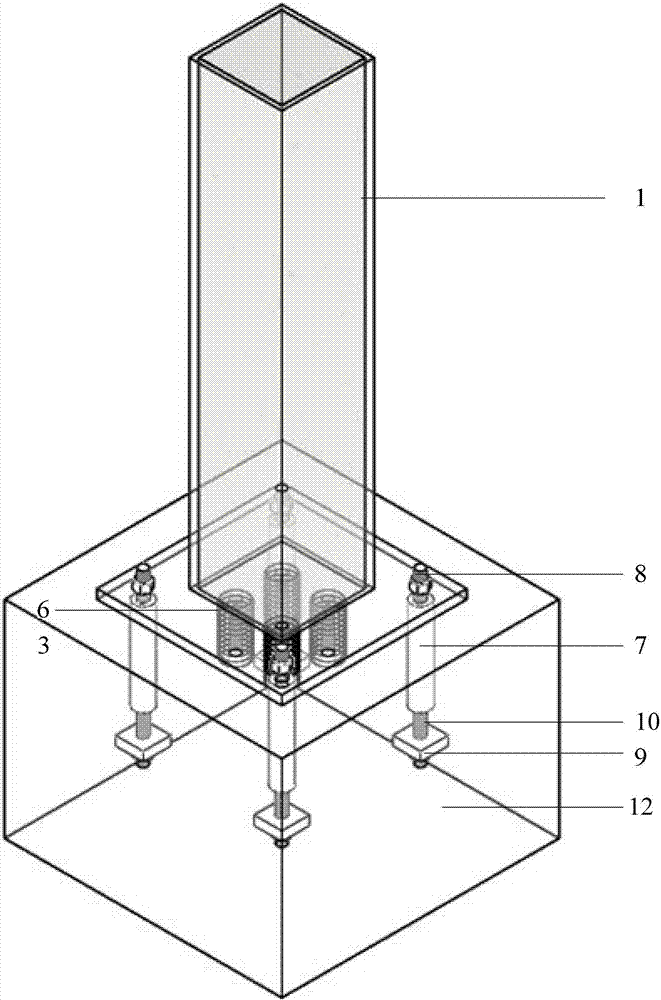
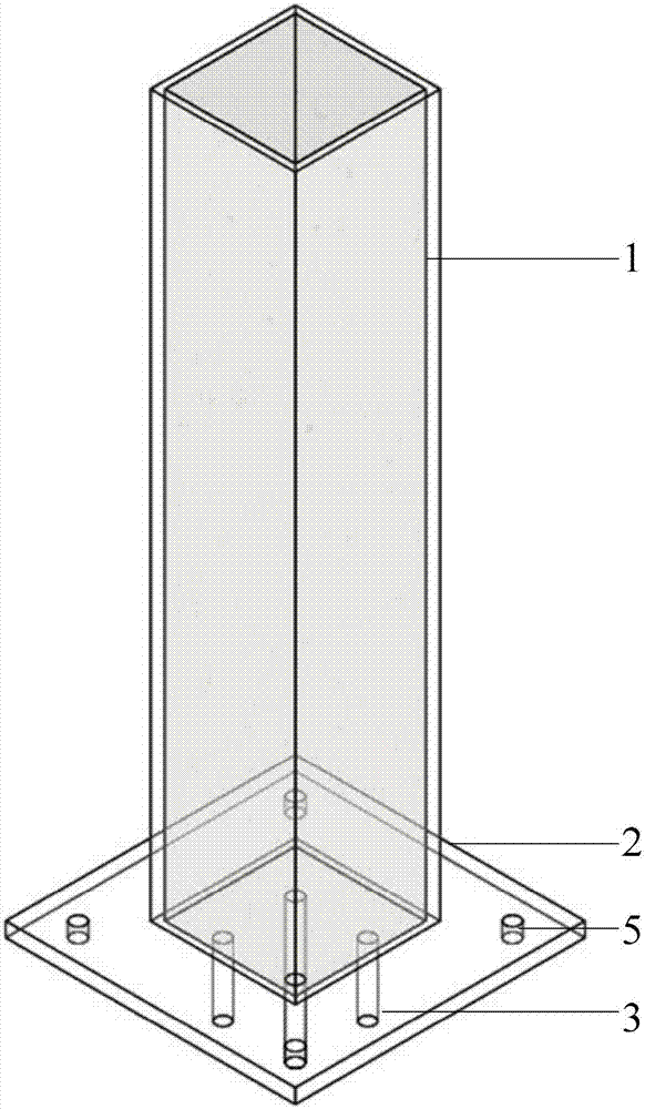
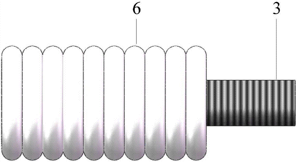
[0027] The present invention will be described in further detail below in conjunction with the accompanying drawings and specific installation methods. The main components of the structural system include steel pipe concrete columns 1, high-strength screws 2, column end plates 3, plastic films 4, reserved screw holes 5, pre-embedded corrugated sleeves 6, threaded steel sleeves through the core 7, upper connecting screws 8, Steel anchor plate 9, lower end screw rod 10, nut 11, prefabricated reinforced concrete foundation 12, the construction sequence of structure of the present invention is as follows:

[0028] 1. In addition to the need to pour self-compacting cement base on the pre-embedded corrugated casing of the foundation on site, all components are prefabricated in the factory. For the column section size and steel pipe wall thickness, column end plate, anchor bolt number and spacing, and the configuration of the concrete foundation Steel bars shall meet the structural r...


PUM


Abstract

The invention discloses a detachable prefabricated assembly type square steel tube concrete column base joint. The detachable prefabricated assembly type square steel tube concrete column base joint comprises a square steel tube concrete column and a reinforced concrete foundation, wherein a bottom plate is welded to the end of the square steel tube concrete column, high-strength screw rods are welded to the inner side of the bottom plate, the high-strength screw rods as anti-shearing members are connected with pre-embedded corrugated sleeves of the foundation, and meanwhile, the welding screw rods are coated with plastic films. Preformed screw holes are formed in the outer side of the steel tube bottom plate and used for making splice anchor bolts and the bottom plate connected. When the square steel tube concrete column base joint is assembled, connecting screw rods are screwed into the upper ends of through tang inner screw-thread steel sleeves through the preformed screw holes in the bottom plate respectively, so that splicing between the square steel tube concrete column and the foundation is achieved. When the steel tube concrete column is disassembled and replaced, the screw rods are screwed out, the anti-shearing members are taken out, high-strength castables in the corrugated sleeves are removed, and then the steel tube concrete column can be disassembled and replaced. All the members used in the square steel tube concrete column base joint can be assembled and connected on the site, site welding work and formwork engineering are reduced, the building industrialization assembly efficiency is improved, and the new architectural concepts that building members save energy and are environmentally friendly and detachable are embodied.

Description

technical field [0001] The invention belongs to the technical field of engineering structures, and is particularly applicable to the field of on-site splicing operations between square steel pipe concrete columns and foundations in middle and high-rise building structures. Background technique [0002] my country's building construction is mainly based on on-site construction. This traditional production method is not highly industrialized, the design and construction are relatively extensive, the quality of construction products is unstable, the construction efficiency is low, the demand for labor is large, the loss of materials and the amount of construction waste And energy consumption is relatively large, can not meet the sustainable development construction requirements of energy conservation and environmental protection. With the acceleration of the process of "construction industrialization and housing industrialization" in our country, the trend of housing industriali...

Claims


Application Information

Patent Timeline
IPC IPC(8): E02D27/42E04B1/41
CPCE02D27/42E04B1/41E04B1/4157E04B1/4164
Inventor 刘艳芝康黎静李智崔鹏飞
Owner HUNAN UNIV
Learn More