Industrial production smoke cooling, dust reducing and waste heat recycling device and method
A technology of waste heat recovery device and heat exchange device, which is applied in separation methods, chemical instruments and methods, waste heat treatment, etc., can solve the problems of fluctuation of production process, low dust removal efficiency, and insignificant cooling effect, so as to achieve stable product quality and improve product quality. The effect of stable product quality and easy centralized collection
- Summary
- Abstract
- Description
- Claims
- Application Information
AI Technical Summary
Problems solved by technology
Method used
Image

Examples
Embodiment 1
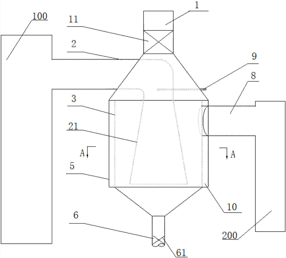
[0047] The waste heat recovery device for flue gas cooling and dust reduction in industrial production in this embodiment includes: an air guide mechanism 5, which can be a vertical or horizontal barrel-shaped structure. This embodiment adopts a vertical barrel-shaped structure with a diameter of 3400 mm and a height of It is 4600mm, which is used to cool down the whole device; inside the air guiding mechanism 5, and the flue gas cooling mechanism 3 with the air guiding mechanism 5 is a cavity ring structure, also in the shape of a vertical barrel, The diameter is 3000mm, and the height is 4000mm. Due to the temperature drop, the density of large particles of smoke and dust will increase, and they will fall on the bottom of the flue gas cooling mechanism 3 to achieve the effect of dust reduction in the first step; and be fixed on the top of the air guide mechanism 5 The heat exchange device 11 inside the air outlet pipe 1 can be a plate or tube heat exchanger, and the heat exch...
Embodiment 2
[0049] The industrial production flue gas temperature reduction and dust reduction waste heat recovery device of this embodiment has the same basic structure as that of Embodiment 1, the differences and improvements are as follows: figure 1 , 3 As shown, the flue gas cooling mechanism 3 is a closed barrel-shaped structure to avoid fluctuations in the flue gas caused by external airflow throughout the process. The dust-laden flue gas introduction pipe 2 penetrates from the top of the barrel-shaped structure and is inserted into the barrel The bottom of the barrel-shaped structure lengthens the flow distance of the flue gas in the entire flue gas cooling mechanism 3, allowing large particles of smoke to have enough time to cool down and fall; the dust-reducing flue gas outlet pipe 8 is fixed on the upper part of the barrel-shaped structure On the side, the dust-reduced flue gas is exported through the pipe; the bottom of the barrel-shaped structure is closed, and communicates wi...
Embodiment 3
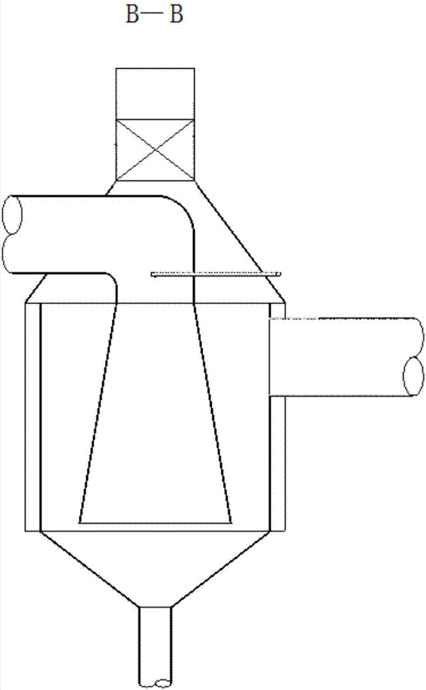
[0051] The basic structure of the waste heat recovery device for industrial production flue gas cooling and dust reduction in this embodiment is the same as that of Embodiment 2, the difference and improvement is that the part of the dust-laden flue gas introduction pipe 2 inserted into the barrel-shaped structure is a trumpet-like shape that gradually opens downwards The opening 21 gradually reduces the airflow velocity of the flue gas, avoids excessive fluctuations in the process due to drastic reduction, and gradually slows down the flow velocity of the dusty flue gas, prolongs the flow time of the flue gas in the entire flue gas cooling mechanism 3, and further allows Large particles of soot have ample time to cool down and fall. The air guide mechanism 5 is in the form of a drum structure with the upper part gradually closed, which is convenient for the hot air after heat exchange to flow out concentratedly for secondary heat exchange and utilization; the diameter is large...
PUM
| Property | Measurement | Unit |
|---|---|---|
| diameter | aaaaa | aaaaa |
| height | aaaaa | aaaaa |
Abstract
Description
Claims
Application Information
 - R&D
- Intellectual Property
- Life Sciences
- Materials
- Tech Scout
- Unparalleled Data Quality
- Higher Quality Content
- 60% Fewer Hallucinations
Browse by: Latest US Patents, China's latest patents, Technical Efficacy Thesaurus, Application Domain, Technology Topic, Popular Technical Reports.
© 2025 PatSnap. All rights reserved.Legal|Privacy policy|Modern Slavery Act Transparency Statement|Sitemap|About US| Contact US: help@patsnap.com