Spiral bevel gear female die tooth surface design method and spiral bevel gear machining method

A technology of spiral bevel gear and design method, which is applied in the field of spiral bevel gear die tooth surface design and spiral bevel gear processing. Meet the design requirements and other issues, achieve the effects of low vibration and noise, avoid secondary processing, and improve processing efficiency

Active Publication Date: 2017-10-20
HENAN UNIV OF SCI & TECH
View PDF5 Cites 9 Cited by
  • Summary
  • Abstract
  • Description
  • Claims
  • Application Information

AI Technical Summary

Problems solved by technology

At present, the processing of spiral bevel gears generally first directly process the large wheel and small wheel according to the design parameters. For the small wheel of the spiral bevel gear, due to its large helix angle, its precision forging cannot be carried out. The current spiral bevel gear Precision forging is mainly carried out for the large wheel. Due to the deformation of the tooth surface of the large wheel after precision forging, the contact performance of the tooth surface contact area a

Method used


Image

  • Spiral bevel gear female die tooth surface design method and spiral bevel gear machining method
  • Spiral bevel gear female die tooth surface design method and spiral bevel gear machining method
  • Spiral bevel gear female die tooth surface design method and spiral bevel gear machining method

Examples


Embodiment Construction

[0034] Embodiments of the present invention will be further described below in conjunction with the accompanying drawings.

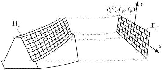
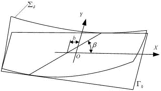
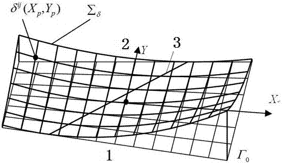
[0035] The specific embodiment of the spiral bevel gear processing method of Gleason system of the present invention, as Figure 1 to Figure 5 As shown, it includes the following steps: First, the small wheel is processed according to the design parameters of the small wheel, and then the parameters of the tooth surface of the concave die corresponding to the tooth surface of the large wheel are obtained through the design method of the tooth surface of the spiral bevel gear tooth surface, that is, the target The coordinates of any point on the tooth surface, and finally according to the parameters of the tooth surface of the tooth surface of the tooth surface of the large wheel, the concave mold (tooth mold) for precision forging of the large wheel of the spiral bevel gear can be processed on the CNC machining center, and then Large wheels are processed...


PUM


Abstract

The invention relates to a spiral bevel gear female die tooth surface design method and a spiral bevel gear machining method. The spiral bevel gear female die tooth surface design method includes the steps: taking tooth surface parameters of an actually-machined small gear as reference parameters; calculating parameters of a large gear tooth surface according to transmission relationships and tooth surface contact properties of a large gear and the small gear and deformation amount after forging of the large gear tooth surface; acquiring parameters of a female die tooth surface for forging the large gear tooth surface according to the parameters of the large gear tooth surface; machining a female die according to the parameters, forging the large gear by the aid of the female die, and enabling the forged large gear tooth surface and a small gear tooth surface to meet preset meshing performance. Secondary repairing and matching of the small gear tooth surface is avoided, the machining process of a spiral bevel gear is simplified, and machining efficiency is improved.

Description

technical field [0001] The invention relates to a design method for the tooth surface of a concave die of a spiral bevel gear and a processing method for the spiral bevel gear. Background technique [0002] Spiral bevel gears are widely used in important mechanical transmission fields such as industry, agriculture, and national defense. Researchers have conducted in-depth studies on its design and processing techniques. With the maturity and popularization of precision forging technology for straight bevel gears, people pay more and more attention to precision forming of spiral bevel gears. The traditional gear cutting process destroys the metal fiber streamline structure, reduces the tooth root bending fatigue strength, tooth surface wear resistance, etc., at the same time, the production efficiency is low, the material utilization rate is low, and the production cost is high. Therefore, it is an inevitable trend to replace the current milling process with precision forgi...

Claims


Application Information

Patent Timeline
IPC IPC(8): G06F17/50B21J5/02B21K1/30
CPCB21J5/02B21K1/305G06F30/17
Inventor 杨建军张华高振山魏冰阳李聚波邓效忠
Owner HENAN UNIV OF SCI & TECH
Why Eureka
Try Eureka