
Microfluid heat radiation channel, heat radiation method and preparation method thereof

A technology of heat dissipation channels and microfluidics, which is applied in the fields of electric solid state devices, semiconductor devices, semiconductor/solid state device components, etc. low difficulty effect

Active Publication Date: 2017-10-20
SOUTHWEST CHINA RES INST OF ELECTRONICS EQUIP
View PDF1 Cites 20 Cited by
  • Summary
  • Abstract
  • Description
  • Claims
  • Application Information

AI Technical Summary

Problems solved by technology

However, this process relies on vacuum coating technology (thermal evaporation, electron beam evaporation and magnetron sputtering, etc.) to prepare the seed layer, which has high processing cost and low processing efficiency.

Method used


Image

  • Microfluid heat radiation channel, heat radiation method and preparation method thereof
  • Microfluid heat radiation channel, heat radiation method and preparation method thereof
  • Microfluid heat radiation channel, heat radiation method and preparation method thereof

Examples


Embodiment 1

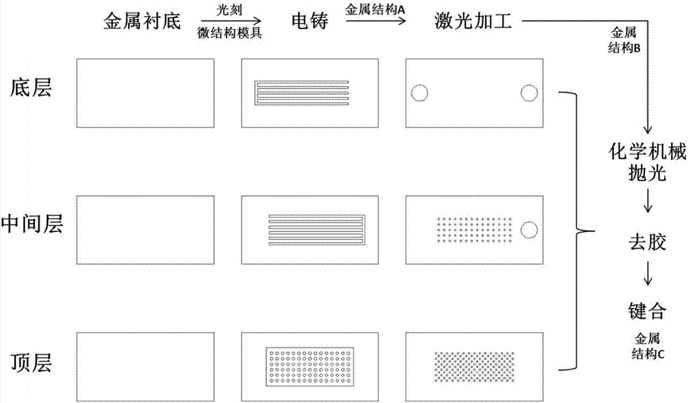
[0050] Step 1: Provide a metal substrate with a surface roughness RMS less than 10 nm.

[0051] Preferably, the metal is copper.

[0052] Preferably, the number of the metal substrates is three, namely the top metal substrate, the middle metal substrate and the bottom metal substrate.

[0053] Step 2: using photoresist or photosensitive dry film on the surface of the three-layer metal substrate to prepare a microstructure mold.

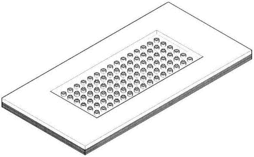
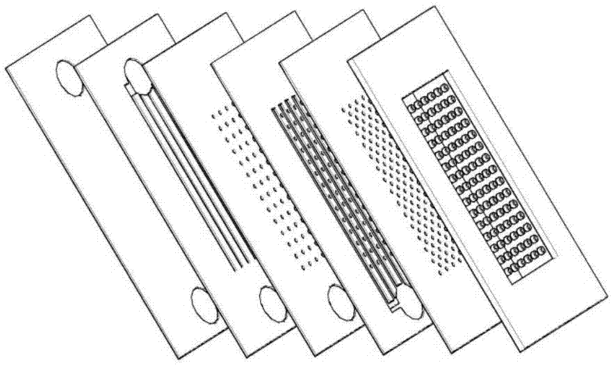
[0054] Step 3: Transfer the structure into a metal structure A (as shown in FIG. 4( a )) through an electroforming process.

[0055] Preferably, the electroforming process is a copper electroforming process.

[0056] Preferably, the metal structure A is a three-layer structure, which are:

[0057] (a) a straight-through reflow channel on the surface of the underlying substrate;

[0058] (b) a straight-through liquid inlet channel on the surface of the intermediate layer substrate;

[0059] (c) Cylindrical bosses on the top substrate surface.

[...


PUM

PropertyMeasurementUnit
surface roughnessaaaaaaaaaa

Abstract

The invention belongs to the field of microelectronic heat radiation technology. For aiming at problems in prior art, the invention provides a microfluid heat radiation channel, a heat radiation method and a preparation method. According to the preparation method, a total metal heat radiation microchannel based on a distributed nozzle structure is realized through processes of photoetching, metal micro-electroforming and metal bonding. The preparation method comprises the steps of preparing corresponding microstructure molds on a bottom layer, an intermediate layer and a top metal substrate by means of a photosensitive material; through a metal micro-electroforming process, transferring the micro-structure molds for preparing a metal microstructure A; performing hole processing on the metal microstructure A through a laser fine machining process, and forming a metal microstructure B with communicating holes; performing mechanical polishing on the metal microstructure B, and forming the microfluid heat radiation channel based on the distributed nozzle structure through a metal bonding process.

Description

technical field [0001] The invention belongs to the technical field of microelectronic heat dissipation, in particular to a microfluid heat dissipation channel, a heat dissipation method and a preparation method. Background technique [0002] With the increase of chip power and the improvement of integration level, the calorific value of the chip increases significantly; the traditional remote heat dissipation technology can no longer meet the heat dissipation requirements of high-power chips. Insufficient heat dissipation will result in reduced chip efficiency and even lead to chip failure; therefore, new cooling techniques are necessary. [0003] Microfluidic cooling technology is an emerging embedded chip-level enhanced cooling technology. It directly cools the chip through micro-scale continuous fluid, which minimizes the impact of thermal resistance between heat sinks on the heat dissipation efficiency in the remote heat dissipation mode, thereby greatly improving the ...

Claims


Application Information

Patent Timeline
Patent Type & Authority Applications(China)
IPC IPC(8): H01L23/367H01L23/373H01L23/473
CPCH01L23/367H01L23/3735H01L23/3736H01L23/473
Inventor 张剑刘志辉林玉敏束平
Owner SOUTHWEST CHINA RES INST OF ELECTRONICS EQUIP
Learn More