Ellipsoidal-reflector-based material complex dielectric constant high temperature testing device and method

A technology of ellipsoidal reflector and complex dielectric constant, which is applied in the direction of measuring device, dielectric property measurement, electric variable measurement, etc., can solve the problems of high test cost, inconvenient maintenance, processing accuracy of volatile samples, etc., and achieve guaranteed test Effects of stability and precision, low cost of use and maintenance, and low sample placement requirements

Active Publication Date: 2017-10-24
成都恩驰微波科技有限公司
View PDF7 Cites 7 Cited by
  • Summary
  • Abstract
  • Description
  • Claims
  • Application Information

AI Technical Summary

Problems solved by technology

However, in this patent, since the waveguide is directly heated, the deformation, volatilization and electrical performance changes of the waveguide after heating will have a great impact on the test accuracy, and the processing accuracy of the sample is required to be high.
In the patent of "a high-temperature complex permittivity measuring device for dielectric materials" with the notification number CN102393490A, the short-circuit surface of the traditional waveguide terminal short-circuit is changed to a choke flange structure, which ensures the connection between the short-circuit surface of the terminal and the waveguide at high temperature. Good electrical contact between them, but there are still problems of waveguide heat deformation, volatilization and high precision of sample processing
In the patent of "free-space terminal short-circuit system for temperature-varying test of dielectric properties of dielectric materials" with the notification number CN103344841A, a free-space terminal short-circuit method was proposed, and a dielectric focusing antenna was used instead of a waveguide to realize the separation of the heating part and the test sensor. To a certain extent, the reliability and life of the test sensor are improved, and the processing accuracy of the sample is not high. However, because this method uses polytetrafluoroethylene as the lens of the focusing antenna, the lens will be affected by thermal radiation during the high temperature test and the sensor will be damaged. The stability becomes poor, and the dielectric lens cannot withstand high-temperature thermal radiation at ultra-high temperature, and the impurities volatilized by the metal heating element at high temperature are easy to adhere to the surface of the lens, resulting in poor focusing effect of electromagnetic waves, which in turn affects test accuracy
[0004] As mentioned above, the waveguide terminal short-circuit method in the traditional complex dielectric constant high-temperature test method is easy to cause deformation and pollution of the waveguide, resulting in poor reusability of test fixtures, high test costs, inconvenient maintenance, and high processing requirements for samples to be tested. ; and the free-space terminal short-circuit method using a dielectric lens as a focusing antenna cannot be used for ultra-high temperature tests due to the limited thermal radiation that the dielectric lens can withstand, and the volatiles attached to the surface of the lens will cause the electromagnetic wave focusing effect to deteriorate, thus affecting the test. accuracy of results

Method used


Image

  • Ellipsoidal-reflector-based material complex dielectric constant high temperature testing device and method
  • Ellipsoidal-reflector-based material complex dielectric constant high temperature testing device and method
  • Ellipsoidal-reflector-based material complex dielectric constant high temperature testing device and method

Examples


Embodiment Construction

[0035] Embodiments of the present invention are described below through specific examples, and those skilled in the art can easily understand other advantages and effects of the present invention from the content disclosed in this specification.

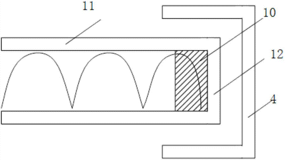
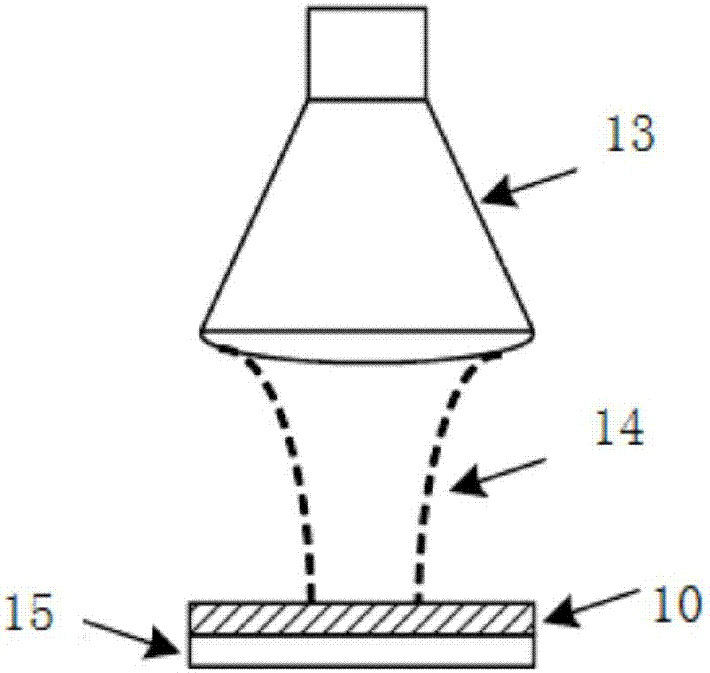
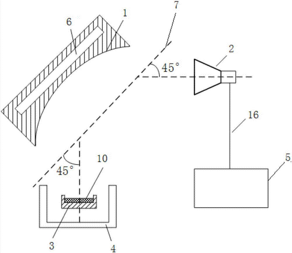
[0036] Such as image 3 As shown, the material complex permittivity high-temperature test device based on the ellipsoid reflector includes a metal ellipsoid reflector 1, a horn antenna 2, a metal crucible 3, a high-temperature furnace 4 and a vector network analyzer 5, and the horn antenna 2. Connect to the vector network analyzer 5 through a microwave cable 16; the aperture field of the horn antenna 2 is evenly distributed and the side lobe level is more than 20dB smaller than the main lobe level, and has a lower side lobe level; as Figure 4 As shown, the reflection surface 9 of the ellipsoid reflector 1 is a part of the spheroid, such as Figure 5 and Figure 6 As shown, the reflective surface 9 of the ellipsoid reflector 1 is o...


PUM


Abstract

The invention provides an ellipsoidal-reflector-based material complex dielectric constant high temperature testing device and testing method. The ellipsoidal-reflector-based material complex dielectric constant high temperature testing device includes an ellipsoidal reflector, a horn antenna, a metal crucible, a high temperature furnace and a vector network analyzer, wherein the vector network analyzer is connected with the horn antenna through a microwave cable; the reflection plane of the ellipsoidal reflector is one part of a rotation ellipsoid; a long axis of the rotation ellipsoid and the axis of the horn antenna form a 45DEG included angle, and the long axis of the rotation ellipsoid and the normal of the metal crucible form a 45DEG included angle; the phase center of the horn antenna is located at one focus of the ellipsoidal reflector; and the center of the upper surface of the metal crucible is located at the other focus of the ellipsoidal reflector. The ellipsoidal-reflector-based material complex dielectric constant high temperature testing device has the advantages of high testing accuracy, high testing stability, low usage and maintenance cost and low demand for sample arrangement. Besides, the ellipsoidal-reflector-based material complex dielectric constant high temperature testing device can guarantee stability of the focusing wave beam amplitude and phase during the high temperature testing process as the ellipsoidal reflector is used, so that the accuracy of the test result can be guaranteed.

Description

technical field [0001] The invention belongs to the technical field of microwave and millimeter-wave dielectric material testing, and relates to a high-temperature and ultra-high-temperature complex dielectric constant test system for materials, in particular to a free-space terminal short-circuit method test system and method. Background technique [0002] Microwave heat-transparent materials are dielectric materials, which are widely used in the manufacture of aircraft radome and antenna window. As the speed of the aircraft becomes faster and faster, the operating temperature of the microwave thermal wave-transparent material is also higher and higher, up to 2000 degrees Celsius, and the change law of its dielectric properties with temperature is also more complicated. These changes will affect the microwave performance of heat-transparent materials, and have a great impact on the transmission and reception of electromagnetic wave signals by aircraft antennas. Therefore, ...

Claims


Application Information

Patent Timeline
Patent Type & Authority Applications(China)
IPC IPC(8): G01R27/26
CPCG01R27/2617
Inventor 李恩张云鹏李建桥李亚峰余承勇郑虎高勇
Owner 成都恩驰微波科技有限公司
Why Eureka
Try Eureka