Motor driver and stator direct current excitation motor system

A motor-driven, maximum current technology, used in the control of electromechanical transmissions, control systems, and generators, etc., can solve the problems of low power density and large number of switching tubes, and achieve the effect of reducing costs and reducing power electronic devices.

Active Publication Date: 2017-10-24
HUAZHONG UNIV OF SCI & TECH
View PDF5 Cites 8 Cited by
  • Summary
  • Abstract
  • Description
  • Claims
  • Application Information

AI Technical Summary

Problems solved by technology

[0003] In view of the defects of the prior art, the object of the present invention is to provide a motor drive device and a stator DC excitation motor system, aiming at solving the technical problems of large number of switching tubes and low power density used in the existing motor drive device

Method used


Image

  • Motor driver and stator direct current excitation motor system
  • Motor driver and stator direct current excitation motor system
  • Motor driver and stator direct current excitation motor system

Examples


Embodiment Construction

[0036] In order to make the object, technical solution and advantages of the present invention clearer, the present invention will be further described in detail below in conjunction with the accompanying drawings and embodiments. It should be understood that the specific embodiments described here are only used to explain the present invention, not to limit the present invention.

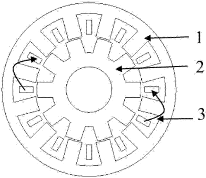
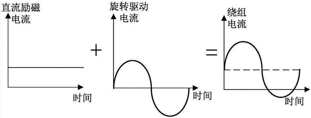
[0037] figure 1 A schematic structural diagram of a DC biased sinusoidal current motor driven by the embodiment of the motor drive device provided by the present invention. Such as figure 1 As shown, the DC bias sinusoidal current motor includes a stator 1, a rotor 2, a winding 3, and other general structural parts of the motor such as a shaft, a casing, an end cover, and a position encoder. The characteristics of this motor are: the current passed through the winding includes sinusoidal AC component and DC component. The reluctance motor adopts a single-layer fractional slot non-overlapping conc...


PUM


Abstract

The invention discloses a motor driver and a stator direct current excitation motor system. The motor driver includes a plurality of phase bridge arms and one neutral point bridge arm, wherein one phase bridge arm, the neutral point and one phase winding of the driven motor form a current loop; through control of the conduction direction and the conduction time of the phase bridge arm, the voltage at the winding end being adjacent to the phase bridge arm and the voltage duration time are controlled; through control of the conduction direction and the conduction time of the neutral point bridge arm, the voltage at the winding end being adjacent to the neutral point bridge arm end and the voltage duration time are controlled, so that control of the voltage magnitude and the voltage time at two ends of the winding can be realized and control of the current magnitude and the current direction at two ends of the winding can be realized; and as the neutral point bridge arm is used as a common bridge arm, N-1 bridge arms are reduced and furthermore 4N-4 switch elements are reduced, so that the cost of the driver is greatly reduced and the power density is improved.

Description

technical field [0001] The invention belongs to the field of inverse AC motors and drive control, and more specifically relates to a motor drive device and a stator DC excitation motor system. Background technique [0002] The application of power electronic converters as controllers is the main method of modern electric drives. Permanent magnet motors have the advantages of high power density, high efficiency, and high power factor. However, permanent magnet motors have problems such as high cost of permanent magnets and irreversible demagnetization of excitation. The traditional switched reluctance motor has a simple structure and low cost, but due to its unique power supply method, there is a large current peak at the moment the switch is turned off, so the vibration and noise of the motor are very large. In addition, the torque ripple of the motor Also larger. These shortcomings affect the use of switched reluctance motors in some occasions that require high vibration ...

Claims


Application Information

Patent Timeline
Patent Type & Authority Applications(China)
IPC IPC(8): H02P25/16H02P25/02H02P21/00
Inventor 蒋栋李安高子晗贾少锋曲荣海李大伟
Owner HUAZHONG UNIV OF SCI & TECH
Why Eureka
Try Eureka