Automatic device for drill tool welding

A technology of automation equipment and drilling tools, which is applied in welding equipment, welding equipment, auxiliary welding equipment, etc., can solve the problems of low efficiency and relatively high labor intensity requirements, and achieve the effect of high efficiency in the processing process, not easy to break down, and slow down the labor intensity

Active Publication Date: 2017-10-31
ZHEJIANG PULANKA ROCK TOOLS CO LTD
View PDF6 Cites 3 Cited by
  • Summary
  • Abstract
  • Description
  • Claims
  • Application Information

AI Technical Summary

Problems solved by technology

Nowadays, people usually use people to manually transfer the newly assembled drilling tools from multiple devices one by one, which requires relatively high labor intensity and low efficiency.

Method used


Image

  • Automatic device for drill tool welding
  • Automatic device for drill tool welding
  • Automatic device for drill tool welding

Examples


Embodiment 1

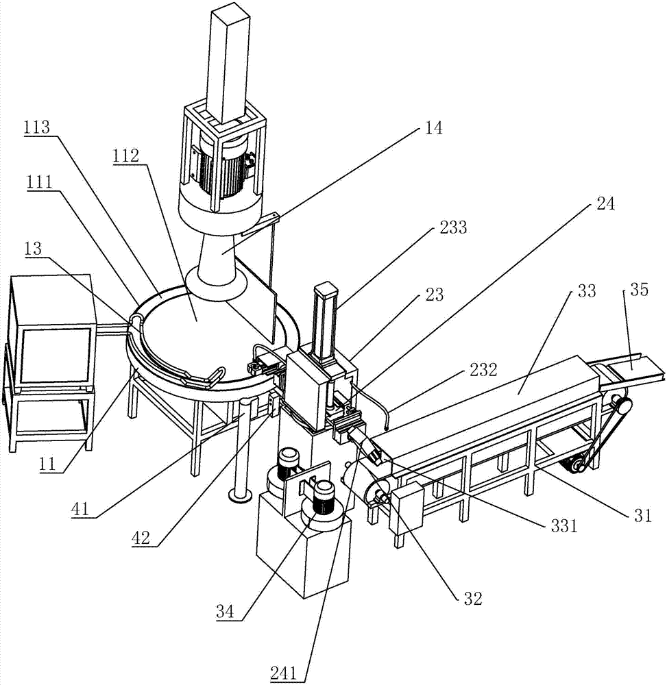
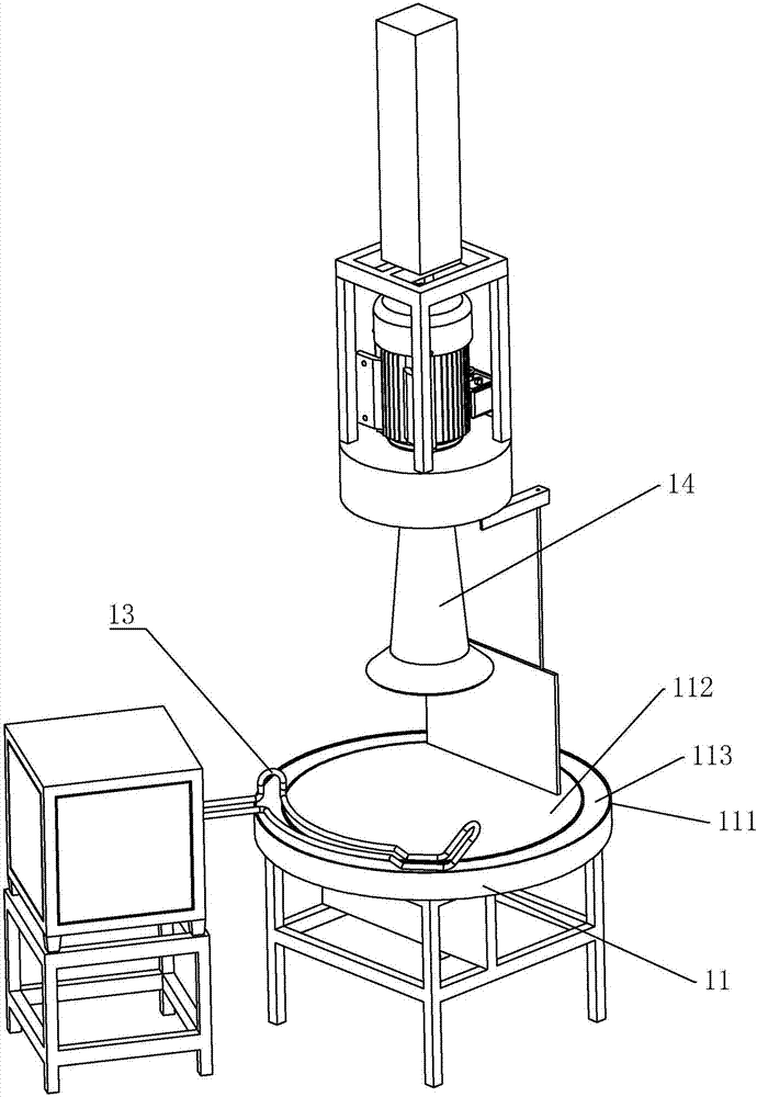
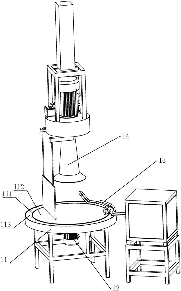
[0034] Such as figure 1 As shown, a heating mechanism for brazing tool welding includes a rotatable turntable 11 and a drive motor 12 that drives the turntable 11 to rotate. The turntable 11 is horizontally arranged and installed on the frame. rotation. The turntable 11 is circular, and the placement area 111 is arranged on the turntable 11, and the placement area 111 is located on the outer edge of the turntable 11, and the placement area 111 is an annular structure. The placement area 111 is provided with a recessed area 112 , and the recessed area 112 is recessed downwards in an arc shape. Wherein, the placement area 111 is provided with an annular installation groove 113, the width of the installation groove 113 is consistent with the drill tool, after the drill tool is put into the installation groove 113, it can be consistent with the width of the drill tool, and the depth of the installation groove 113 is not very Deep, to ensure that the drilling tool can be effectiv...

Embodiment 2

[0040] Such as Figure 4 As shown, a manipulator for grabbing drilling tools includes a rotatable turntable 21, a rotating motor 22 for driving the turntable 21 to rotate, the turntable 21 is horizontally arranged, the turntable 21 is installed on the frame, and the rotating motor 22 is a servo motor, which can adjust and control the rotation angle and direction of rotation of the turntable 21 through the program in the control box, so as to ensure that the turntable 21 can rotate at an appropriate angle and direction as required. Turntable 21 is fixedly provided with fixed frame 23, and fixed frame 23 is provided with rotating arm 24, and the structure of fixed frame 23 is a structure that both sides are open and hollow, and rotating arm 24 is a elongated penetrating fixed frame 23. The fixed frame 23 is provided with a vertical sliding guide column 231, and the number of the sliding guide column 231 is two, both of which are symmetrical about the center of the fixed frame 23...

Embodiment 3

[0045] A cooling mechanism for drilling tools, the cooling mechanism includes a base frame 31, the base frame 31 is provided with a freely rotatable cooling belt 32, a driving mechanism for driving the cooling belt 32 to rotate, the cooling belt 32 is made of steel, The cooling belt 32 is like a steel crawler, and the driving mechanism is a motor and a toothed plate. The toothed plate is installed on the bottom frame 31 through a shaft. The number of the toothed plates is two. The cooling belt 32 is installed on the toothed plate to form a waist shape. Structure. The motor can drive the chainring to rotate through the chain, thereby ensuring that the cooling belt 32 can continuously rotate. Underframe 31 is provided with the wind collecting hood 33 of both sides opening, and wind collecting hood 33 is covered on the top of cooling belt 32, and wind collecting hood 33 side is provided with blower 34, and the air outlet of blower 34 is facing the opening of wind collecting hood ...


PUM


Abstract

The invention discloses an automatic device for drill tool welding. According to the technical scheme of the automatic device, the automatic device is characterized in that the automatic device comprises a heating mechanism used for a drill tool, a cooling mechanism used for natural cooling, and a detection head, a mechanical arm used for grabbing the drill tool from the heating mechanism and transferring the drill tool to the cooling mechanism from the heating mechanism is arranged between the heating mechanism and the cooling mechanism, the detection head is in signal connection with the mechanical arm, and after the drill tool completely heated by the heating mechanism enters a detection area of the detection head, the detection head drives the mechanical arm to transfer the completely-heated drill tool to the cooling mechanism. The heating mechanism can conduct heating processing on the drill tool; and by arranging the detection head, the mechanical arm can be operated to effectively grab the completely-heated drill tool, and therefore the drill tool is transferred to the cooling mechanism and then cooled on the cooling mechanism, people only need to place completely-assembled products on the heating mechanism, the tedious and complex product transfer labor of people is avoided, and meanwhile the production efficiency is also ensured.

Description

technical field [0001] The invention relates to brazing tool processing equipment, in particular to a brazing tool welding automation equipment. Background technique [0002] Due to the continuous development of society, the demand for energy is also increasing. Today, with the rapid development of the mining industry, the advancement of mining technology and the development of pile engineering. It will definitely bring broad development space to the utilization of mineral resources and pile driver construction. With the rapid development of the machinery manufacturing industry, high-efficiency and high-power roadheaders and engineering pile drivers are no longer the bottleneck restricting the development of mining, tunneling, piling, and engineering construction. How to improve the comprehensive performance of the cutting elements in the cutting head is very important. , with the increase in the amount of deep mining in the industrial and mining industry, the hard abrasive...

Claims


Application Information

Patent Timeline
Patent Type & Authority Applications(China)
IPC IPC(8): B23K31/02B23K37/00
CPCB23K31/02B23K37/00B23K2101/20
Inventor 沈国华
Owner ZHEJIANG PULANKA ROCK TOOLS CO LTD
Why Eureka
Try Eureka