Method for machining thin-wall bearing rings by adopting digital controlled lathe

A technology of thin-walled bearings and CNC lathes, which is applied to bearing components, shafts and bearings, metal processing equipment, etc., and can solve problems such as difficult to ensure ring size accuracy, shape accuracy, position accuracy, surface roughness, and deformation of bearing rings , to achieve the effect of ensuring the consistency of precision, reducing stress deformation and meeting process requirements

Inactive Publication Date: 2017-11-03
AVIC HARBIN BEARING
View PDF6 Cites 1 Cited by
  • Summary
  • Abstract
  • Description
  • Claims
  • Application Information

AI Technical Summary

Problems solved by technology

[0006] The purpose of the present invention is to solve the problem that the existing thin-walled bearing rings are easy to produce under the action of clamping force, cutting force and cutting heat generated in the cutting process due to the thin wall of the bearing ring during the processing process. Deformation, there is a problem that it is difficult to ensure the dimensional accuracy, shape accuracy, position accuracy and surface roughness of the ferrule

Method used


Image

  • Method for machining thin-wall bearing rings by adopting digital controlled lathe
  • Method for machining thin-wall bearing rings by adopting digital controlled lathe
  • Method for machining thin-wall bearing rings by adopting digital controlled lathe

Examples


specific Embodiment approach 1

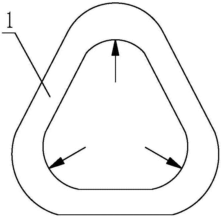
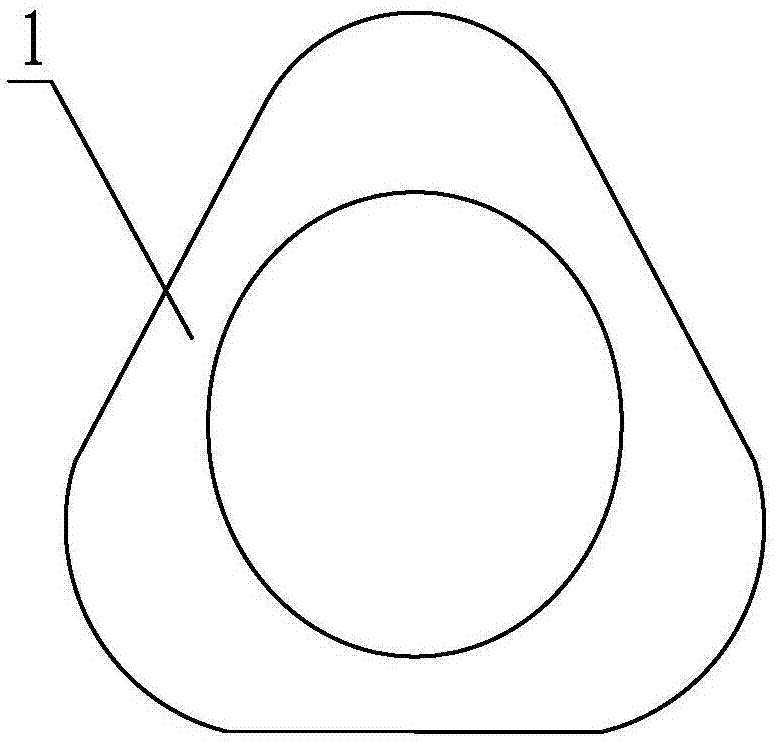
[0030] Specific implementation mode one: combine Figure 1 to Figure 4 Describe this embodiment, a thin-walled bearing ring CNC lathe processing method of this embodiment, the method includes the following steps:

[0031] Step 1. Clamping of thin-walled bearing ring 1:

[0032] When the thin-walled bearing ring 1 is processed by CNC lathe, the first jaw 2 of the CNC lathe is used to clamp the thin-walled bearing ring 1, and the included angle of the first jaw 2 is α, α=110°-130 °;

[0033] Step 2, rough turning the outer diameter and inner diameter of the thin-walled bearing ring 1:

[0034] The thin-walled bearing ring 1 is rough turned by the first numerically controlled blade, and the linear speed of the first numerically controlled blade is v 1 , v 1 =160m / min-180m / min, the feed rate is f 1 , f 1 =0.22mm / r; the sharp corner radius of the first CNC blade is R 1 , R 1 =1.5mm-1.2mm, turning allowance is Z 1 ,Z 1 =0.6mm-0.8mm,

[0035] Step 3, finish turning the out...

specific Embodiment approach 2

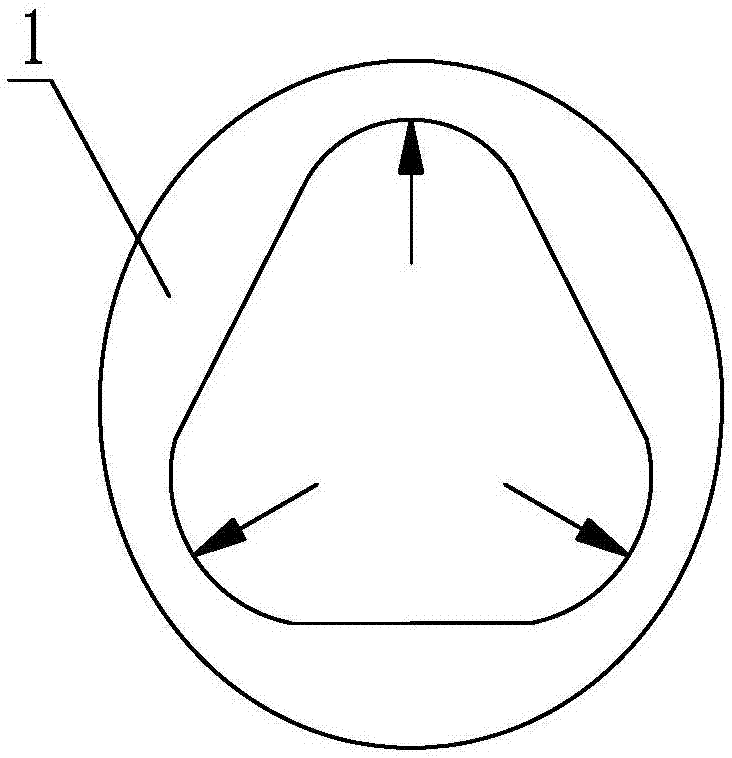
[0039] Specific implementation mode two: combination Figure 5 To describe this embodiment, the included angle α of the first clamping jaw 2 in Step 1 of this embodiment is 120°. With such arrangement, the first clamping jaw 2 with an included angle of 120° makes the clamping state of the bearing ring 1 just not slipping, and the clamping force is the smallest, and the clamping effect is the best. The contact area between the first jaw 2 and the ring 1 is increased to ensure that under the same clamping force, the deformation range of the ring 1 is effectively reduced, and the dimensional accuracy and accuracy of the bearing ring 1 are improved. shape precision. Other compositions and connections are the same as in the first embodiment.

specific Embodiment approach 3

[0040] Specific implementation mode three: combination Figure 1 to Figure 3 Describe this embodiment, the linear velocity v of the first numerically controlled blade in the step 2 of this embodiment 1 =170m / min, the sharp corner radius R of the first CNC blade 1 = 1.3mm, turning allowance Z 1 = 0.7 mm. Such setting effectively reduces the deformation range of the ferrule 1, ensures the surface roughness and accuracy requirements of the rough-turned thin-walled bearing ferrule 1, and improves the positional accuracy and dimensional accuracy of the rough-turned bearing ferrule. Other compositions and connections are the same as those in Embodiment 1 or Embodiment 2.


PUM


Abstract

The invention relates to a numerically controlled lathe processing method for a thin-walled bearing ring, which relates to the field of mechanical processing of the bearing ring. The present invention solves the problem that the existing thin-walled bearing rings are easily deformed under the action of clamping force, cutting force and cutting heat generated in the cutting process due to the thin wall of the bearing rings during the processing process. It is difficult to guarantee the dimensional accuracy, shape accuracy, position accuracy and surface roughness of the ferrule. The method of the present invention comprises the following steps: step 1, when using a numerically controlled lathe to process the thin-walled bearing ring, use the first jaw to clamp the thin-walled bearing ring; step 2, rough turning the thin-walled bearing ring Outer diameter and inner diameter; Step 3, finish turning the outer diameter and inner diameter of the thin-walled bearing ring; Step 4, fine-turning the inner diameter of the outer diameter of the thin-walled bearing ring, so far, the entire turning process of the thin-walled bearing ring is completed . The invention is used for turning processing of thin-walled bearing rings.

Description

technical field [0001] The invention relates to the field of mechanical processing of bearing rings, in particular to a numerically controlled lathe processing method for thin-walled bearing rings. Background technique [0002] In order to meet the use requirements of bearings, many bearing rings are of thin-walled structure. When the diameter ratio of the outer surface to the inner surface of the bearing ring is less than or equal to 1.143, it is called a thin-walled bearing ring. The biggest difficulty in processing thin-walled bearing rings is the deformation during processing, and the deformation is caused by clamping the inner or outer diameter. The thin-walled bearing ring can be regarded as an elastic body. Although the machined surface of the bearing ring is round, due to elastic deformation, the bearing ring will appear roundness deformation in the process of restoring the original shape after loosening. The bearing ring The state when the inner diameter is clamped...

Claims


Application Information

Patent Timeline
IPC IPC(8): B23B5/00B23B1/00
CPCB23B5/00B23B1/00B23B2215/12
Inventor 李迎丽朱磊范志成周英侽
Owner AVIC HARBIN BEARING
Why Eureka
Try Eureka