A magnetic field heat treatment furnace with stable performance

A heat treatment furnace and stable technology, applied in heat treatment furnaces, heat treatment equipment, furnaces, etc., can solve problems such as magnetic instability of workpieces, and achieve the effects of convenient maintenance or maintenance, uniform heating, and stable magnetic properties of workpieces

Active Publication Date: 2018-08-28
四川西南工业炉有限公司
View PDF10 Cites 0 Cited by
  • Summary
  • Abstract
  • Description
  • Claims
  • Application Information

AI Technical Summary

Problems solved by technology

[0003] Based on the above technical problems, the present invention provides a magnetic field heat treatment furnace with stable performance, thereby solving the technical problem of magnetic instability of the workpiece after being treated in the existing magnetic field heat treatment furnace

Method used


Image

  • A magnetic field heat treatment furnace with stable performance
  • A magnetic field heat treatment furnace with stable performance

Examples


Embodiment 1

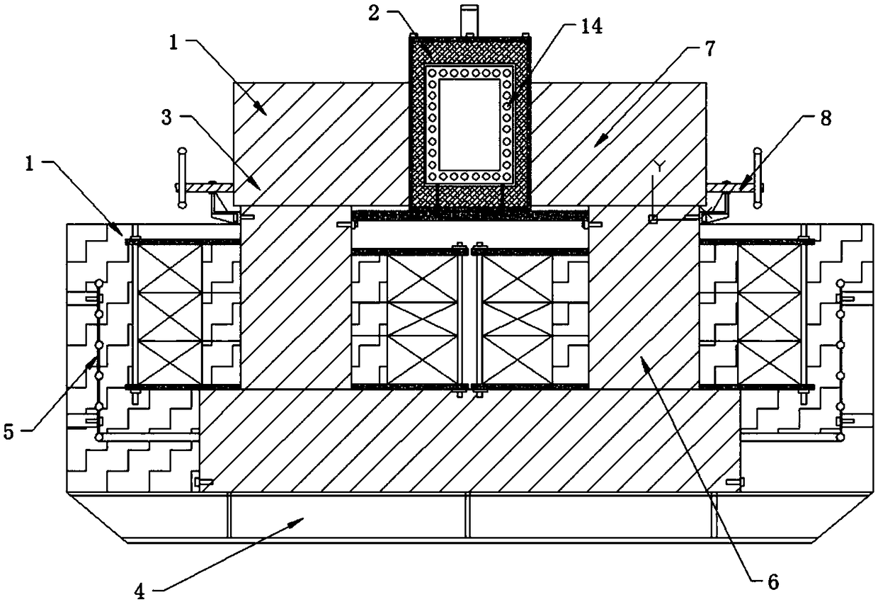
[0026] A magnetic field heat treatment furnace with stable performance is characterized in that it includes a furnace body 1, a heating furnace 2, an electromagnetic system 3, a cooling oil tank 4 and a water cooling circulation system 5; the electromagnetic system 3, the cooling oil tank 4 and the water cooling circulation system 5 are all It is arranged inside the furnace body 1; the cooling oil tank 4 is arranged inside the furnace body 1, and the water cooling circulation system 5 passes through the inside of the cooling oil tank 4 and is connected to the tap water pipe;

[0027] The electromagnetic system 3 includes a lower magnetic pole 6 arranged in the cooling oil tank 4 and two opposite upper magnetic poles 7 movably connected to the upper part of the furnace body 1; the heating furnace 2 is movably arranged between the two upper magnetic poles 7; The upper part of the furnace body 1 is located outside the ends of the two upper magnetic poles 7, and is respectively pro...

Embodiment 2

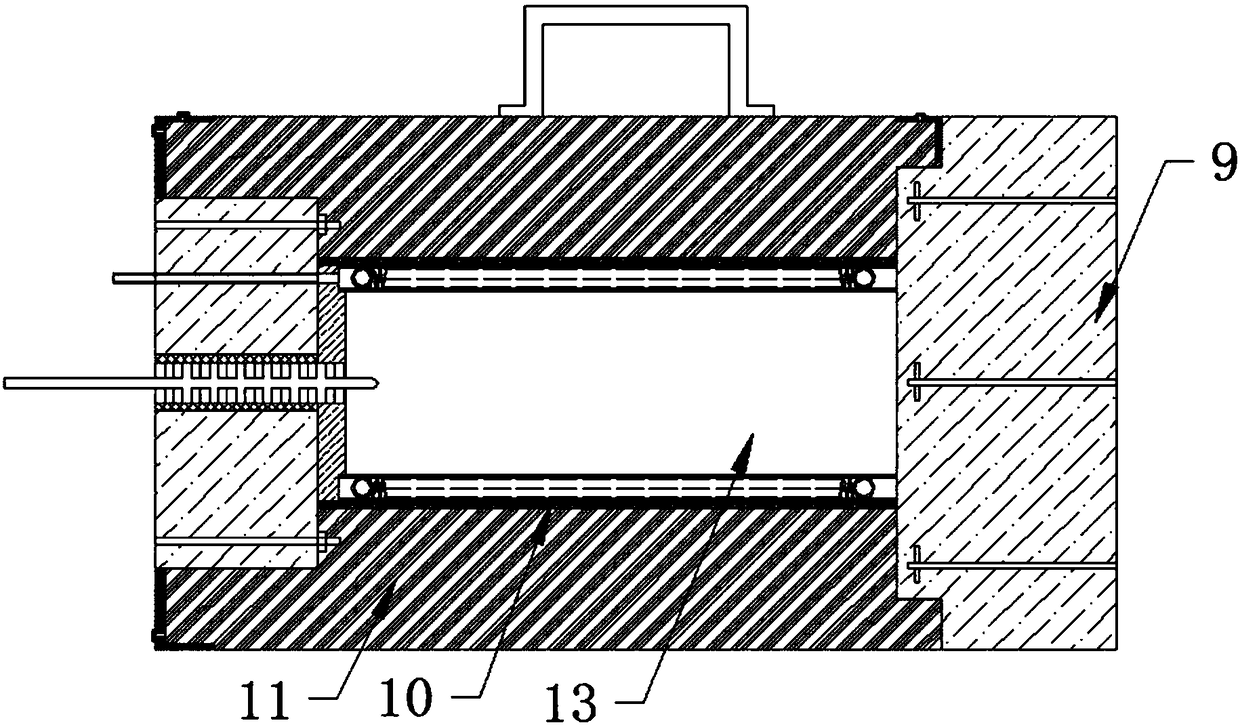
[0030] This embodiment is further optimized based on Embodiment 1. The heating element is a Φ2.0mm resistance wire drawn by high-temperature electrothermal material Cr20Ni80 and made into a spiral structure with a middle diameter of 11mm, a spiral pitch of 4.0mm, and a total number of turns of 2106.5 turns , the heating element can make the workpiece to be magnetized be heated more uniformly in the heating furnace, so that the magnetism of the processed workpiece is more stable.

Embodiment 3

[0032] This embodiment is further optimized based on Embodiment 1. Before the high-alumina aluminum silicate fibers of the furnace lining 11 are manufactured and assembled, they are cured to ensure that the furnace lining 11 does not shrink during use, increase the stability of the furnace lining 11, and increase the service life. , Reduce maintenance costs.


PUM

PropertyMeasurementUnit
diameteraaaaaaaaaa

Abstract

The invention relates to a magnetic field heat treatment furnace, and discloses a magnetic field heat treatment furnace stable in performance. The magnetic field heat treatment furnace comprises a furnace body, a heating furnace, an electromagnetic system, a cooling oil tank and a water cooling circulating system. The electromagnetic system comprises a lower magnetic pole arranged on the lower portion in the cooling oil tank and two oppositely-arranged upper magnetic poles movably connected to the upper portion of the furnace body. The heating furnace is movably arranged between the two upper magnetic poles. Adjusting handles for adjusting the positions of the upper magnetic poles are arranged at the positions, located on the outer sides of the ends of the two upper magnetic poles, of the upper portion of the furnace body correspondingly. Multiple rotary round holes are evenly distributed in the inner wall of a furnace core, and the inner sides of the rotary round holes communicate with a hearth. According to the magnetic field heat treatment furnace stable in performance, the radiation effect on the hearth is enhanced through the rotary round holes, and the magnetism of treated workpieces is more stable; and air gaps between the two upper magnetic poles and the heating furnace can be adjusted through the adjusting handles, it is guaranteed that enough magnetic field intensity exists in the heating furnace, and the magnetism of the treated workpieces is more stable.

Description

technical field [0001] The invention relates to a magnetic field heat treatment furnace, in particular to a magnetic field heat treatment furnace with stable performance. Background technique [0002] Amorphous alloy material is a new type of alloy material that came out in the 1970s. It adopts international advanced ultra-quick cooling technology to directly cool liquid metal at a cooling rate of 1×10⁶°C / s to form a solid thin strip with a thickness of 0.02-0.04mm, and obtain atomic Amorphous alloy structure with short-range order and long-range disorder in arrangement and combination. This alloy has many unique performance characteristics, such as excellent magnetism, corrosion resistance, wear resistance, high hardness, high strength, high resistivity, etc. . Due to its excellent performance and simple production process, it has become the focus of research, development and application of materials science circles at home and abroad since the 1980s. It is used in electr...

Claims


Application Information

Patent Timeline
Patent Type & Authority Patents(China)
IPC IPC(8): C21D1/04C21D9/00H01F13/00
CPCC21D1/04C21D9/00H01F13/00
Inventor 杜超
Owner 四川西南工业炉有限公司
Why Eureka
Try Eureka