Efficient soft-packed battery heat control device and cooling method

A soft pack battery, thermal control technology, applied in chemical instruments and methods, batteries, secondary batteries, etc., can solve the problems of insufficient resistance to cooling water corrosion resistance, easy to be corroded and perforated, etc.

Pending Publication Date: 2017-11-14
谢彦君
View PDF10 Cites 5 Cited by
  • Summary
  • Abstract
  • Description
  • Claims
  • Application Information

AI Technical Summary

Problems solved by technology

[0006] Under the premise of taking into account the forming ability of aluminum-plastic film and aluminum foil, at the same time, the aluminum-plastic film used for packaging batteries (battery) in the prior art is resistant to antifreeze coolant (abbreviated as antifreeze, whose main components are ethylene glycol and water) or antifreeze The

Method used


Image

  • Efficient soft-packed battery heat control device and cooling method
  • Efficient soft-packed battery heat control device and cooling method
  • Efficient soft-packed battery heat control device and cooling method

Examples


Embodiment 1

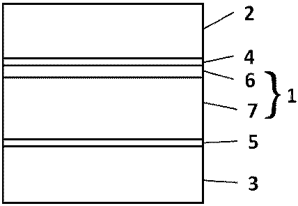
[0123] as attached figure 1 An aluminum-plastic film is provided, which includes an aluminum foil layer 1 and plastic layers 2 and 3 compounded on both sides of the aluminum foil layer, wherein the aluminum foil layer 1 is composed of a 3-series aluminum alloy aluminum foil layer 7 (core material) and 7 It is formed by compounding the aluminum alloy aluminum foil layer 6 (leather material). For example, 3003 aluminum alloy and 7072 aluminum alloy are used for compounding, and the 7072 aluminum alloy layer 6 is compounded on the outside of the 3003 aluminum alloy layer 7 . In other words, the aluminum-plastic film is formed by sequentially stacking a heat-sealing layer, a 3003 aluminum foil layer, a 7072 aluminum foil layer and a nylon layer, wherein the aluminum foil layer and the plastic layer are bonded with a traditional adhesive. In other words, the layers of the aluminum-plastic film from the inside to the outside are: heat-sealing layer, adhesive layer, 3003 aluminum fo...

Embodiment 2

[0128]The structure of this embodiment is roughly similar to that of Embodiment 1. The aluminum alloy layer 1 is also formed by a composite of a core material 7 and a skin material 6, and the skin material 6 is an anode protection layer. The difference is that the 7072 aluminum alloy is replaced by the 3003 aluminum alloy with Zn added (3003+1%Zn or 3003+1.5%Zn in the table below) as the sacrificial anode layer. The potential of 3003+1%Zn is about -0.83V to -0.89V, which is lower than that of 3003 core material.

[0129] Table 1 Alloy chemical composition

[0130]

Embodiment 3

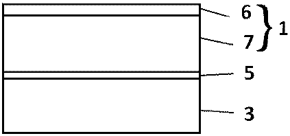
[0132] as attached figure 2 A second aluminum-plastic film is provided, which includes an aluminum foil layer 1 and a thermoplastic resin film layer 3 composited inside the aluminum foil layer, wherein the aluminum foil layer is a composite layer aluminum foil, and the aluminum foil layer contains a core material and is located outside the core material The corrosion potential of the skin material of the aluminum foil layer is lower than that of the core material. Further, the core material of the aluminum foil layer is formed of corrosion-resistant aluminum alloy or pure aluminum. For example, the composite aluminum foil layer 1 is formed by compounding the 3-series aluminum foil layer 7 (such as 3003) and the 7-series aluminum foil layer 6 (such as 7072). Only the inner side of the aluminum foil layer 1 is compounded with a thermoplastic resin film layer 3 (also called a heat-sealing layer 3, such as CPP), without an external nylon protective layer. Compared with the alum...


PUM

PropertyMeasurementUnit
Corrosion potentialaaaaaaaaaa
Thicknessaaaaaaaaaa

Abstract

The invention provides a soft-packed battery heat control device, particularly relates to the soft-packed battery heat control device capable of being soaked in cooling water and provides a corresponding package material in allusion to the defect of low corrosion resistance of the battery package material in the prior art. The package material is formed by an aluminum foil layer with resistance to corrosion of cooling water and a plastic layer on the surface of the aluminum foil layer.

Description

technical field [0001] The invention relates to a thermal control device for a pouch battery, in particular to a thermal control device for a pouch battery that can be immersed in cooling water, such as a water cooling system that can be used in the field of vehicle power batteries and energy storage batteries. Background technique [0002] Thermal management technology is one of the core technologies of soft-pack power batteries. There have been many thermal management technical solutions and efforts in this field, but thermal management is still one of the bottlenecks restricting the development of this industry. The demand for efficient thermal management Still very urgent. Most of the existing pouch battery cooling methods are air cooling, oil cooling and water cooling; for example, the water cooling scheme introduced in CN201210016348.0 uses a water cooling plate or cooling tube to contact the battery to exchange heat, and this heat exchange method The contact thermal ...

Claims


Application Information

Patent Timeline
IPC IPC(8): H01M2/02H01M10/613H01M10/625H01M10/6555H01M10/6557H01M10/6567B32B15/088B32B15/20B32B33/00C22C21/02C22C21/00C22C21/10H01M50/105H01M50/119H01M50/121H01M50/124H01M50/128H01M50/129H01M50/136H01M50/211
CPCH01M10/613H01M10/625H01M10/6555H01M10/6557H01M10/6567B32B15/088B32B15/20B32B33/00C22C21/00C22C21/02C22C21/10H01M10/627H01M10/6568B32B7/06B32B7/12B32B15/043B32B15/08B32B27/06B32B27/34B32B2457/10B32B2457/18B32B2307/714B32B2307/50H01M2220/10H01M2220/20H01M50/124H01M50/1245H01M50/105H01M50/129H01M50/211H01M50/128H01M50/119H01M50/136H01M50/121H01M10/647Y02E60/10
Inventor 不公告发明人
Owner 谢彦君
Why Eureka
Try Eureka