Porous titanium cervical fusion cage with HA coating and preparation method of fusion cage

A fusion device and porous titanium technology, applied in the direction of coating, additive manufacturing, manufacturing tools, etc., can solve the problems of increased risk of trabecular fracture, slow integration speed, and unstable fixation, and achieve excellent early osseointegration effects, firmness and Connection method, effect of reducing the risk of arm breakage

Inactive Publication Date: 2017-11-17
维度(西安)生物医疗科技有限公司 +1
View PDF5 Cites 18 Cited by
  • Summary
  • Abstract
  • Description
  • Claims
  • Application Information

AI Technical Summary

Problems solved by technology

However, these traditional intervertebral fusion devices have many limitations in clinical application: PEEK material is a biologically inert material, and the surface of the material is wrapped by a layer of fibrous tissue after implantation in the body, and the bone-material interface is not strong enough, which is prone to fusion failure
[0004] Although there have been a few clinical cases of using 3D printed porous titanium fusion cages for cervical spine fusion, there are still some problems to be solved in the application process: First, due to the limitation of the accuracy of the existing metal 3D printing technology, it is still difficult to use metal 3D printing technology. 3D printing technology directly prepares a precise thread structure. Therefore, unlike solid fusion cages, which are usually fixed by screw connections

Method used


Image

  • Porous titanium cervical fusion cage with HA coating and preparation method of fusion cage
  • Porous titanium cervical fusion cage with HA coating and preparation method of fusion cage
  • Porous titanium cervical fusion cage with HA coating and preparation method of fusion cage

Examples


Embodiment Construction

[0028] The present invention will be described in further detail below in conjunction with the accompanying drawings.

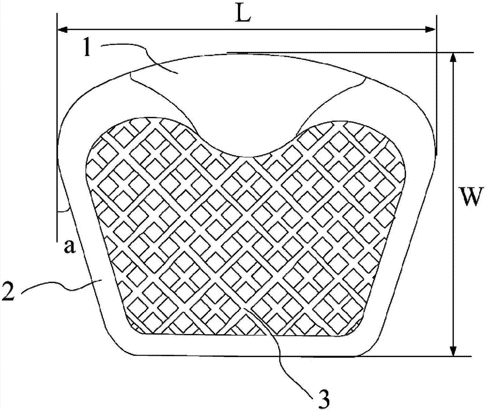
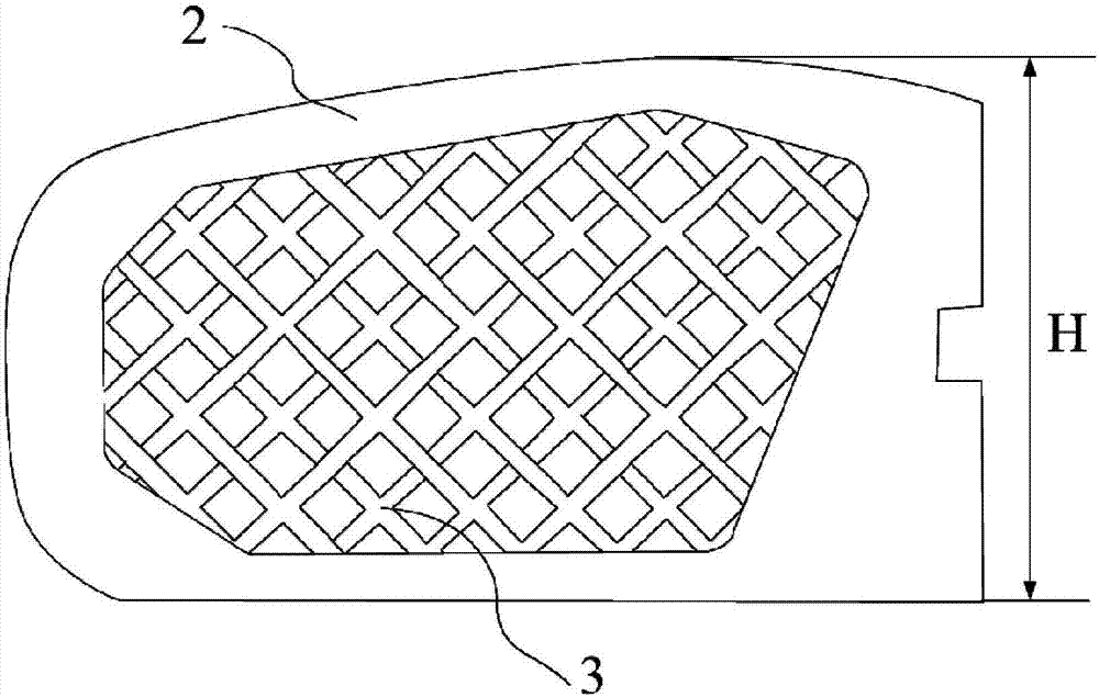
[0029] Such as figure 2 , image 3 The specifications of the wedge-shaped intervertebral fusion cage shown are: length (L): 13-16mm, width (W): 11-13mm, height (H): 5-8mm, wedge angle (angle shown in a): 17° .

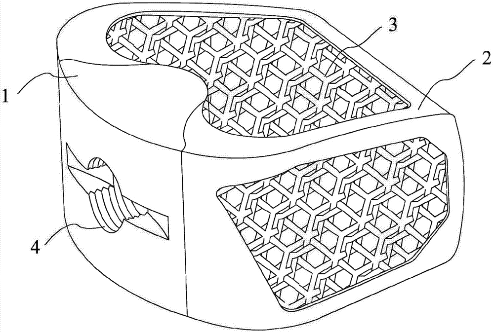
[0030] see Figure 1-4 , the present invention includes a circular arc-shaped solid titanium alloy structure 1 in the middle of the rear, a solid smooth titanium alloy thin-walled structure 2 similar to a bullet-shaped structure in the front, and a fusion device composed of a porous structure 3 filled therebetween. The center of the titanium alloy structure 1 is provided with a threaded groove 4 for connecting the fusion device to the implanted handle during the operation. The porous structure 3 is a regular 12-hedron porous structure with a porosity of 75%, a pore diameter of 400-800 microns, and a trabecular diameter of 300-400 microns. The tra...


PUM

PropertyMeasurementUnit
Wall thicknessaaaaaaaaaa
Apertureaaaaaaaaaa
Central thicknessaaaaaaaaaa

Abstract

The invention discloses a porous titanium cervical fusion cage with a hydroxyapatite (HA) coating and a preparation method of the fusion cage. The fusion cage is composed of an entity framework structure and a porous structure, wherein the entity framework structure is filled with the porous structure. The front portion of the fusion cage is of a structure similar to a bullet head, all edges of the fusion cage are covered with entity smooth titanium alloy thin wall, and the risk that in the implanting process, fusion cage edge small beams are subjected to stress concentration, and arm breaking is caused can be reduced. The central part of the rear portion of the fusion cage is of an arc-shaped entity titanium alloy structure with the thickness being 3 mm or above, and a threaded hole and a groove are machined in the arc-shaped entity titanium alloy structure in a second stage machining mode and used for making the fusion cage connected to an implanting handle during an operation. A thread and the groove can provide a connection mode which is firmer and more reliable than a clamping mode, and implanting is conducted conveniently during the operation. The surfaces of all the small beams of the porous structure of the fusion cage are covered with the hydroxyapatite (HA) coating with the thickness being about 100-500 micrometers, and a more excellent early osseointegration effect can be provided.

Description

technical field [0001] The invention belongs to the field of spinal fusion and internal fixation, and in particular relates to a porous titanium cervical fusion device with HA coating and a preparation method thereof. Background technique [0002] Intervertebral disc herniation and cervical instability caused by degenerative cervical spondylosis are common spinal surgery diseases. Those who fail conservative treatment generally require cervical intervertebral fusion. At present, polyether ether ketone (PEEK) material or solid titanium alloy material intervertebral fusion cage is mainly used for cervical intervertebral fusion. However, these traditional intervertebral fusion devices have many limitations in clinical application: PEEK material is a biologically inert material, and the surface of the material is wrapped by a layer of fibrous tissue after implantation in the body, and the bone-material interface is not strong enough, which is prone to loose and lead to fusion f...

Claims


Application Information

Patent Timeline
IPC IPC(8): A61F2/44A61F2/30
CPCA61F2/30767A61F2/30942A61F2/4455A61F2002/30774A61F2002/3093A61F2002/30952A61F2002/30976A61F2002/30985A61F2310/00023A61F2310/00796A61F2/447A61F2002/3092A61F2002/4495
Inventor 李海漪伍苏华郭征
Owner 维度(西安)生物医疗科技有限公司
Why Eureka
Try Eureka