A sintering flue gas denitrification process based on sintering flue gas circulation and soot catalysis

A technology of sintering flue gas and denitrification, which is applied in the field of sintering flue gas denitrification process and flue gas denitrification process, can solve the problems of low denitrification operation cost of sintering flue gas waste heat recovery rate, waste heat of sintering flue gas waste, and large investment in flue gas denitrification, etc. Achieve the effect of saving external heat sources and catalysts, large dust content, and reducing post dust

Active Publication Date: 2020-06-19
WUHAN WUTUO TECH
View PDF8 Cites 0 Cited by
  • Summary
  • Abstract
  • Description
  • Claims
  • Application Information

AI Technical Summary

Problems solved by technology

[0017] The purpose of the present invention is to solve the problems of waste heat waste of sintering flue gas in the existing sintering system, large investment and high cost of flue gas denitrification, and provide a simple process flow, no external denitrification catalyst for self-catalytic denitrification of dust, and recovery rate of waste heat of sintering dust Sintering flue gas denitrification process based on sintering flue gas circulation and soot catalysis, which is high in size, small in floor space, environmentally friendly, low in investment in denitrification equipment, and low in denitrification operating costs

Method used


Image

  • A sintering flue gas denitrification process based on sintering flue gas circulation and soot catalysis
  • A sintering flue gas denitrification process based on sintering flue gas circulation and soot catalysis

Examples


Embodiment Construction

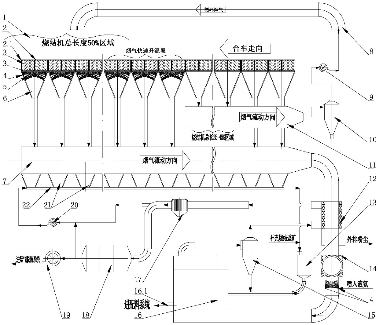
[0047] see figure 2 , including a sintering machine 2, a bellows 6 is provided under the trolley 2.1 of the sintering machine 2, and the outlet at the bottom of the bellows 6 is connected to the flue gas pipeline, and the sintering machine 2 is sequentially divided into an ignition section, a head section, a smoke Gas rapid heating section and tail section 4 areas, the flue gas pipeline is composed of main flue 7 and circulating flue gas main flue 11, the tail section, flue gas rapid heating section and ignition section of the sintering machine 2 The air box 6 below the area is connected to the main flue 7, and the bellows 6 below the nose section area is connected to the main flue 11 of circulating flue gas; wherein, the bottom of the main flue 7 is provided with a main flue powder hopper 21, and the main flue powder The bottom of the hopper 21 is connected to a dust pneumatic conveying pipe 22 , and the outlet of the dust pneumatic conveying pipe 22 is connected to the flui...


PUM


Abstract

The invention relates to a sintering flue gas denitration technology based on sintering flue gas circulation and flue dust catalysis. According to the technology, sintering flue gas penetrates a sintered material layer, a basic material, a fine-toothed comb arranged on the bottom of the trolley of a sintering machine, and an air bellow under the trolley under the effect of the suction force of a high pressure draught fan and enters a flue gas pipeline. Along the moving direction of the trolley, the sintering machine is divided into four areas: an ignition section, a machine head section, a flue gas rapid temperature rising section, and a machine tail section. The particles in the sintering flue gas of the machine tail section and the flue gas rapid temperature rising section deposit in the air bellow and flue gas pipeline and then enter a main flue powder hopper. The particles in the main flue powder hopper is delivered to a particle material chamber through a dust pneumatic transmission pipe by pneumatic transmission and then delivered into a fluidized bed denitration reactor to carry out denitration catalysis. The technical process is simple, the dust catalytic denitration can be performed without any purchased denitration catalyst; the waste heat recovery rate is high, the occupied area is small, the technology is environmentally friendly, the denitration equipment investment is little, and the denitration operation cost is low.

Description

technical field [0001] The invention relates to a flue gas denitrification process in the field of environmental protection, in particular to a sintering flue gas denitrification process based on sintering flue gas circulation and soot catalysis. Background technique [0002] The sintering flue gas circulation process is to circulate part of the sintering flue gas from the branch pipe of the bellows or a part of the sintering flue gas from the main pipe of the large flue to the upper sealing cover of the sintering machine trolley. Its purpose is to recover the sensible heat and latent heat in the sintering flue gas, reduce fuel consumption, and reduce the emission of flue gas pollutants; when the flue gas circulates to the sintering material layer, the dust part will be adsorbed and retained in the sintering material layer, and NOx Partially degraded, dioxins will be pyrolyzed at high temperature, and CO and CH compounds will undergo secondary combustion during the sintering...

Claims


Application Information

Patent Timeline
Patent Type & Authority Patents(China)
IPC IPC(8): B01D53/86B01D53/56
CPCB01D53/343B01D53/8631B01D2251/2062B01D2255/20738B01D2258/0283
Inventor 吴高明吴晓晖卫书杰
Owner WUHAN WUTUO TECH
Why Eureka
Try Eureka