Nuclear power plant control rod driving mechanism hook jaw and preparation method thereof

A driving mechanism and control rod technology, which is applied in the field of nuclear engineering, can solve problems such as poor stability of manual process control, uneven composition of deposited metal, and coarse structure of surfacing layer, so as to improve connection stability and reduce the probability of falling off. The effect of improving mechanical properties

Active Publication Date: 2017-11-17
CHINA NUCLEAR POWER DESIGN COMPANY +2
View PDF5 Cites 7 Cited by
  • Summary
  • Abstract
  • Description
  • Claims
  • Application Information

AI Technical Summary

Problems solved by technology

However, the existing process has the following disadvantages: 1) The control stability of the manual process is poor, the yield rate is low, and the cost is high; 2) Due to the large amount of heat...

Method used


Image

  • Nuclear power plant control rod driving mechanism hook jaw and preparation method thereof
  • Nuclear power plant control rod driving mechanism hook jaw and preparation method thereof
  • Nuclear power plant control rod driving mechanism hook jaw and preparation method thereof

Examples


Embodiment 1

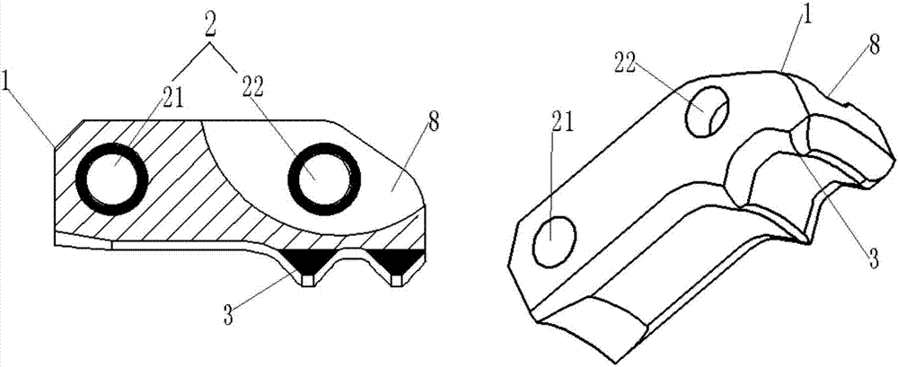
[0039] figure 1 It is a schematic structural diagram of the claw of the nuclear power plant control rod drive mechanism provided by Embodiment 1 of the present invention.

[0040] Such as figure 1 As shown, a gripper of a control rod drive mechanism of a nuclear power plant includes a gripper body and a wear-resistant layer formed by printing two kinds of materials in a layer-by-layer stacking manner; the gripper body includes a gripper base 1, which is arranged on On the hook base 1 and through the shaft pin hole 2 of the hook base 1, the tooth tip 3 on the side wall of the hook base 1 is provided, and the groove 8 is arranged on the side of the hook base 1 away from the tooth tip 3, The wear-resistant layer is respectively formed on the inner peripheral wall of the shaft pin hole 2 and the outer surface of the tooth tip 3 in an inlaid manner. The specific thickness of the wear-resistant layer can be specifically set according to the actual process requirements. The above-me...

Embodiment 2

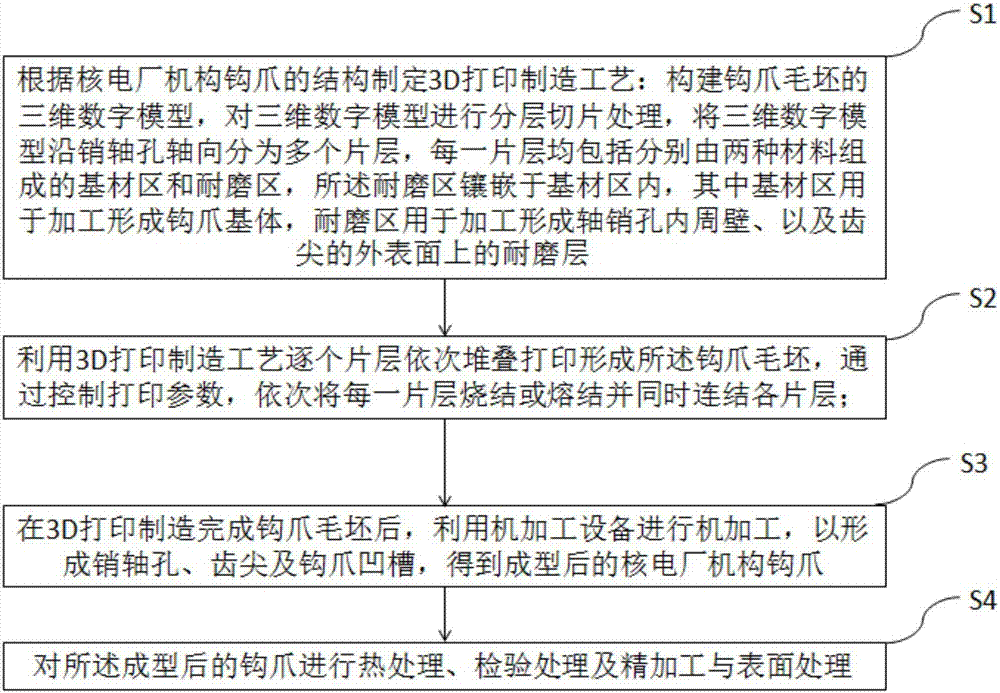
[0046] This embodiment provides a method for preparing the claws of the control rod drive mechanism of a nuclear power plant, which adopts a hybrid manufacturing method in which the blanks of the claws are first printed by a 3D printing manufacturing process, and then machined, such as figure 2 shown, including the following steps:

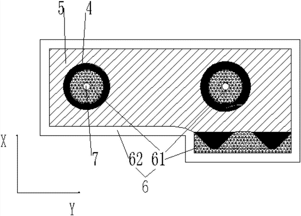
[0047] S1. According to the structure of the claw of the nuclear power plant control rod drive mechanism provided in Embodiment 1, the 3D printing manufacturing process is formulated: the three-dimensional digital model of the blank of the claw is constructed, the three-dimensional digital model is layered and sliced, and the three-dimensional digital model is processed along the pin The axial hole is divided into multiple sheets in the axial direction, combined with image 3 As shown, each sheet layer includes a base material area 5 and a wear-resistant area 4 respectively composed of two materials, and the wear-resistant area 4 is embedded in t...


PUM

PropertyMeasurementUnit
Thicknessaaaaaaaaaa

Abstract

The invention discloses a nuclear power plant control rod driving mechanism hook jaw and a preparation method thereof. The hook jaw comprises a hook jaw body formed by printing two materials by multiple layers in a sequential stacking manner, and wear resisting layers; and the wear resisting layers are formed on the inner peripheral wall of a shaft pin hole and the outer surface of a tooth tip in an embedding manner. The preparation method comprises the following steps: (S1) a 3D printing manufacturing process is formulated according to the structure of the hook jaw; (S2) the 3D printing manufacturing process is used for sequentially stacking multiple layers to print a hook jaw blank; and (S3) after the hook jaw blank is manufactured by 3D printing, machining equipment is used for machining to form the pin shaft hole, the tooth tip and a hook jaw groove to obtain the molded hook jaw. The material organization of the hook jaw is improved by dint of laser metal deposition, so that each part of the hook jaw manufactured by dissimilar materials is more compact and more uniform, the mechanical performance is greatly improved, the surface wear resistance and the impact resistance are improved, and meanwhile, the yield of the hook jaw and the long-time service reliability are improved.

Description

technical field [0001] The invention belongs to the technical field of nuclear engineering, and in particular relates to a claw of a control rod driving mechanism of a nuclear power plant and a preparation method thereof. Background technique [0002] The claws of the control rod drive mechanism (CRDM) in nuclear power plants are the key motion execution parts to realize the functions of lifting, holding and lowering the control rods. They are easy to wear and are prone to failure. [0003] In the prior art, the driving mechanism of the control rods of nuclear power plants adopts single-tooth claws, which use nitrogen-controlling austenitic stainless steel (Z2CN19-10) rods as the substrate, and a layer of cobalt is surfacing on the pin holes and tooth tips of the claws. Base alloy (Stellite6) wear-resistant layer to increase the wear resistance and impact resistance of the surface and improve the service life of CRDM. At present, the wear-resistant layer is made by manual s...

Claims


Application Information

Patent Timeline
IPC IPC(8): B25J15/00B23P13/00B22F3/105B33Y10/00B33Y80/00
CPCB23P13/00B25J15/0033B33Y10/00B33Y80/00B22F10/00B22F10/36B22F10/66B22F10/25B22F10/366B22F10/31B22F10/64Y02P10/25
Inventor 段远刚刘彦章张峰赵建光张飞孙广李石磊谭磊缪鹏陈亮熊志亮
Owner CHINA NUCLEAR POWER DESIGN COMPANY
Why Eureka
Try Eureka