Device and method for testing optical fiber perform refractive index distribution

A technology for refractive index distribution and testing of optical fibers, which is used in testing optical fibers/optical waveguide equipment, testing optical performance, etc., can solve the problems of few attached detection functions, inability to intuitively obtain the refractive index distribution area, and complex error control, and achieve shortened time. The effect of scan test time

Pending Publication Date: 2017-11-17
HENGTONG OPTICAL MATERIAL CO LTD +1
View PDF5 Cites 4 Cited by
  • Summary
  • Abstract
  • Description
  • Claims
  • Application Information

AI Technical Summary

Problems solved by technology

However, the measurement accuracy of this method is not high, and the error control is also relatively complicated, and the refractive index distribution area cannot be obtained intuitively, and there are few detection functions

Method used


Image

  • Device and method for testing optical fiber perform refractive index distribution
  • Device and method for testing optical fiber perform refractive index distribution

Examples


Embodiment Construction

[0033] The implementation of the present invention will be described in detail below in conjunction with the accompanying drawings and examples, so as to fully understand and implement the process of how to apply technical means to solve technical problems and achieve technical effects in the present invention. It should be noted that, as long as there is no conflict, each embodiment and each feature in each embodiment of the present invention can be combined with each other, and the formed technical solutions are all within the protection scope of the present invention.

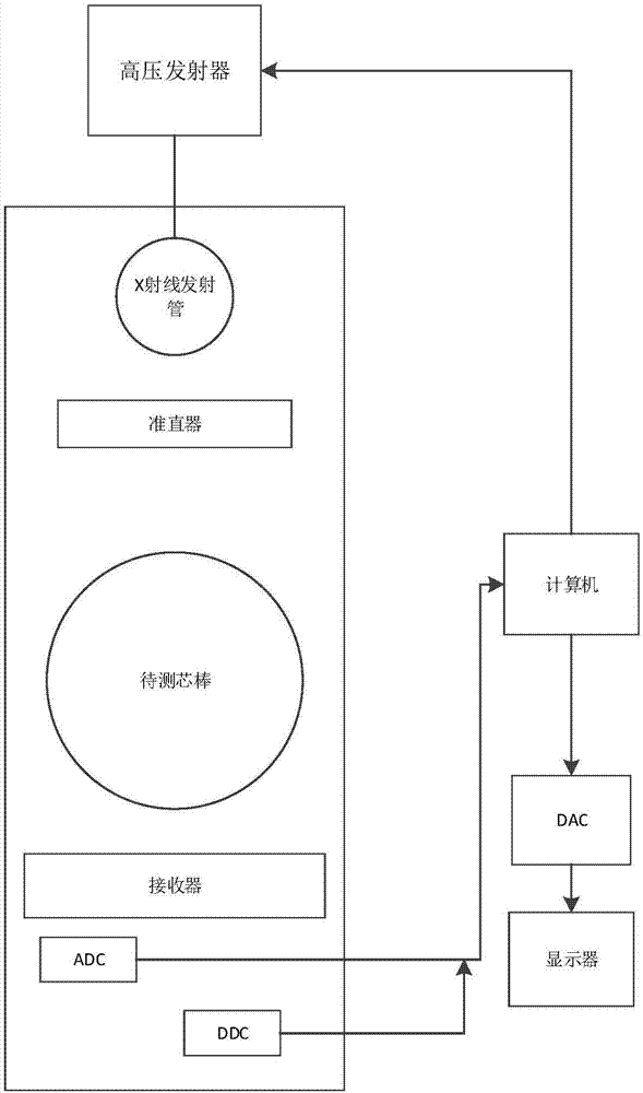
[0034] Specifically, the present invention includes figure 1 In the shown testing system, the testing device is used in combination with the testing method of the present invention to test the refractive index profile of the optical fiber preform.

[0035] 1. Put the mandrel to be tested in the figure 1 The area to be tested is shown and fixed on the area to be tested.

[0036] 2. Turn on the high-voltage ...


PUM


Abstract

The invention discloses a device and method for testing optical fiber perform refractive index distribution. The device comprises a computer, a DAC digital to analog converter (Digital to Analog Converter) connected with the computer, and a high-voltage emitter, wherein the DAC digital to analog converter is directly connected to a displayer; and the high-voltage emitter is connected with an X-ray transmitting tube. The front end of the X-ray transmitting tube is provided with a collimator; and the front end of the collimator is provided with a core rod to be tested. X rays emitted from the X-ray transmitting tube pass through the collimator and the core rod to be tested, and are received by a receiver arranged at the front end of the core rod to be tested; and after being processed by the DAC digital to analog converter and a DDC digital down converter (Direct Digital Control), the X rays are returned to the computer; and a program installed in the computer carries out calculation on the optical fiber perform refractive index distribution. The method comprises the specifically steps: measuring the intensity of the X rays emitted from the X-ray source and the intensity and incident angle of the X rays reaching a detector after attenuation of an optical fiber perform; moving different distances and angles to obtain a plurality of groups of data; and carrying out optical fiber perform image reconstruction based on distribution of attenuation coefficients.

Description

technical field [0001] The invention belongs to a novel method for testing the refractive index distribution of an optical fiber prefabricated rod, and relates to the field of optical fiber manufacturing and detection. Background technique [0002] In recent years, with the popularization of information technology, single-mode optical fiber has been widely used. At present, the beam scanning method is commonly used to measure the refractive index distribution of optical fiber preform. The basic measurement principle is that the thin beam emitted by the laser is irradiated on the optical fiber preform. , according to the characteristics of the measured refractive index of the optical fiber preform gradually changing along the radial direction, the light undergoes continuous refraction inside, and finally exits from the other side of the preform, and is captured by the detector to obtain the exit height. The refractive index distribution of the preform is obtained through mult...

Claims


Application Information

Patent Timeline
Patent Type & Authority Applications(China)
IPC IPC(8): G01M11/02
CPCG01M11/33
Inventor 翟云霄顾志华肖华
Owner HENGTONG OPTICAL MATERIAL CO LTD
Why Eureka
Try Eureka