
Automobile electrical machine heat dissipation fan noise-reduction and anti-vibration system

A motor cooling and fan technology, applied in the field of auto parts, can solve problems such as the deterioration of the working condition of the cooling fan, the increase of the working noise of the cooling fan, and the aggravation of the rotational vibration of the fan blades, so as to improve the NVH performance, avoid the vibration noise, and improve the work. effect of life

Active Publication Date: 2017-11-17
SHANGHAI UNIV OF ENG SCI
View PDF11 Cites 3 Cited by
  • Summary
  • Abstract
  • Description
  • Claims
  • Application Information

AI Technical Summary

Problems solved by technology

The rotational vibration generated by it will cause the motor bearings to wear out gradually, causing the blades of the fan to loosen, thereby aggravating the rotational vibration of the fan blades, increasing the working noise of the cooling fan, and gradually deteriorating the working condition of the cooling fan
That is to say, when the center of gravity of the fan blade does not coincide with the axis of the motor, after the fan rotates, it is equivalent to an oscillator (an oscillator is an eccentric wheel added to the motor shaft). As the use time becomes longer, The gradual wear of the fan bearings will loosen the cooling fins of the fan, which will aggravate the vibration and noise

Method used


Image

  • Automobile electrical machine heat dissipation fan noise-reduction and anti-vibration system
  • Automobile electrical machine heat dissipation fan noise-reduction and anti-vibration system
  • Automobile electrical machine heat dissipation fan noise-reduction and anti-vibration system

Examples


Embodiment

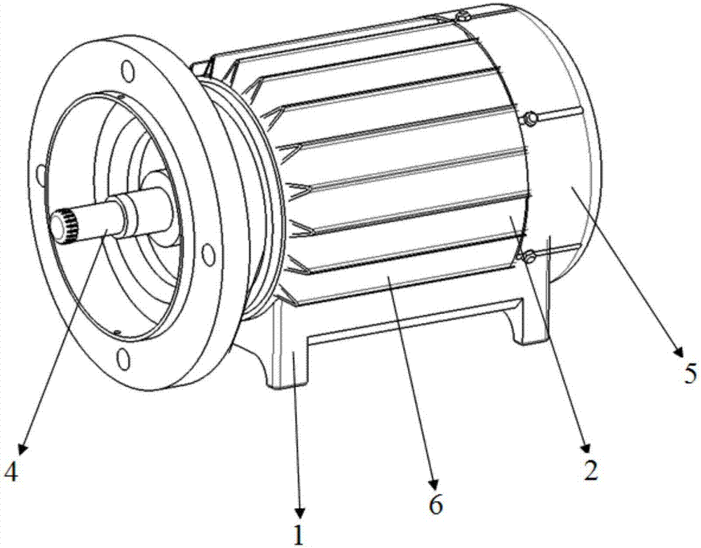
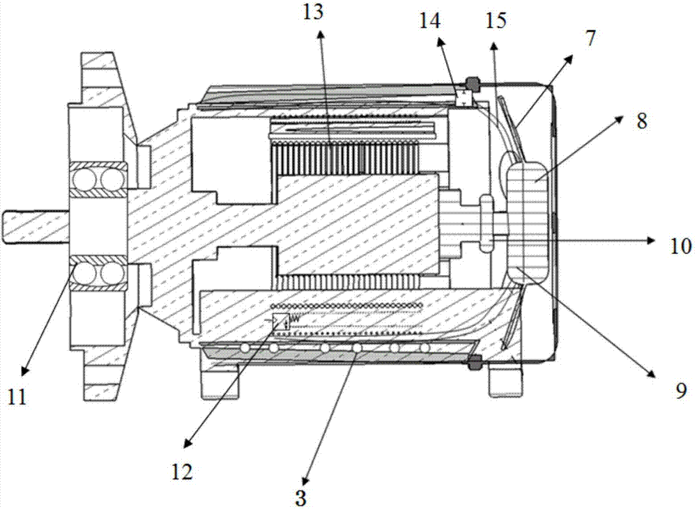
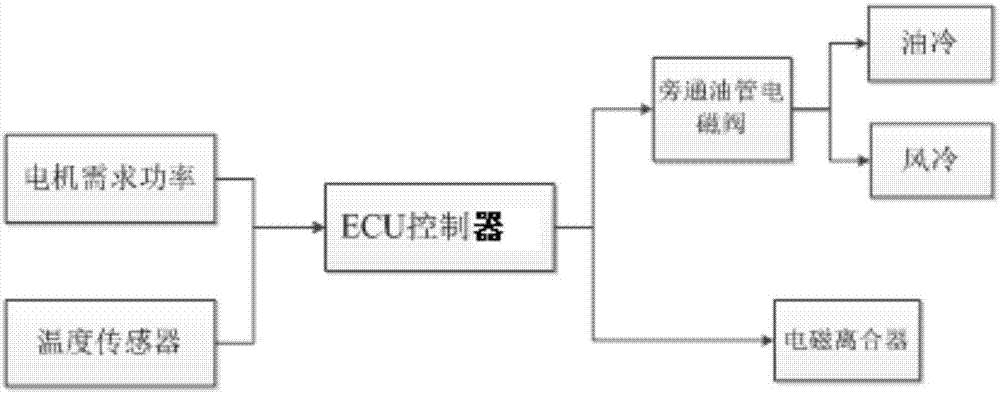
[0030] Such as Figure 1-2 As shown, an automotive motor cooling fan noise reduction and anti-vibration system, the motor includes a base 1, a motor housing 2 arranged on the base 2, a rear cover 5 fixedly connected to the motor housing 2, and evenly arranged on The radiating fins 6 on the motor housing 2, the drive shaft 4 and the electromagnetic coil 13 arranged in the motor housing 2. The device includes a fluid coupling that is connected to the drive shaft 4 in transmission, and is evenly arranged on the fluid coupling The radiating fan 7 around the turbine 8 of the turbocharger, the electromagnetic clutch 10 that connects the pump wheel 9 of the hydraulic coupling with the drive shaft 4, the bypass cooling oil pipe 15 arranged between the electromagnetic coils 13, and the bypass cooling oil pipe The solenoid valve 14 on 15 and the ECU controller electrically connected with the fluid coupling, the electromagnetic clutch 10 and the solenoid valve 14 respectively.

[0031] Whe...


PUM


Abstract

The invention relates to an automobile electrical machine heat dissipation fan noise-reduction and anti-vibration system. An electrical machine includes a pedestal, an electrical machine housing which is arranged on the pedestal, a rear cover which is in fixed connection to the electrical machine housing, heat dissipation fins which are evenly disposed on the electrical machine housing, a drive shaft which is disposed inside the electrical machine housing and an electromagnetic coil. An apparatus includes a hydraulic coupler which is in transmission connection to the drive shaft, heat dissipation blades which are evenly disposed in the periphery of a turbine of the hydraulic coupler, an electromagnetic clutch which brings a pump impeller of the hydraulic coupler and the drive shaft into transmission connection, a bypass cooling pipeline which is arranged in the electromagnetic coil, an electromagnetic valve which is disposed in the bypass cooling pipeline, and an ECU controller which is separate and electrical connection to the hydraulic coupler, the electromagnetic coupler and the electromagnetic valve. Compared with prior art, according to the invention, the system herein realizes heat dissipation by combining oil cooling and air cooling, in combination with a micropunch noise elimination structure, can effectively noise of an automobile electrical machine heat dissipation fan and reduce self vibration.

Description

Technical field [0001] The invention belongs to the technical field of automobile spare parts, and relates to a noise reduction and anti-vibration system, in particular to a noise reduction and anti-vibration system for an automobile motor cooling fan. Background technique [0002] In recent years, pure electric vehicles have developed rapidly, and people's requirements for the superior power of electric vehicles have led to the rapid application of high-power density motors. Subsequently, motor heat dissipation has become the key to the improvement of motor performance. In addition to considering its good heat dissipation effect, the fan's operating noise is also a common concern. Fan noise is the amount of noise generated by the fan when it is working, and is affected by many factors. Fan noise is related to friction and air flow. The higher the fan speed and the greater the air volume, the greater the noise caused, and the vibration of the fan itself is also a factor that c...

Claims


Application Information

Patent Timeline
IPC IPC(8): H02K9/06H02K9/19H02K7/10H02K5/24H02K5/18H02K11/25H02K7/08
Inventor 董启超刘新田祁宏钟
Owner SHANGHAI UNIV OF ENG SCI
Learn More