Supercharge Your Innovation With Domain-Expert AI Agents!

A high-efficiency automatic modulation and boosting circuit and control method

A booster circuit and automatic adjustment technology, applied in electrical components, amplifiers with semiconductor devices/discharge tubes, signal processing, etc., can solve problems such as low booster circuit efficiency

Active Publication Date: 2021-06-08
林其亮
View PDF4 Cites 0 Cited by
  • Summary
  • Abstract
  • Description
  • Claims
  • Application Information

AI Technical Summary

Problems solved by technology

[0004] In view of the above problems, the purpose of the patent of the present invention is to design a high-efficiency automatic modulation boost circuit and control method, which can achieve the dual goals of high efficiency and high output power, and solve the problem of low efficiency of the existing boost circuit

Method used


Image

  • A high-efficiency automatic modulation and boosting circuit and control method
  • A high-efficiency automatic modulation and boosting circuit and control method
  • A high-efficiency automatic modulation and boosting circuit and control method

Examples


Embodiment Construction

[0029] The present invention will be further described in detail below in conjunction with the accompanying drawings and specific embodiments.

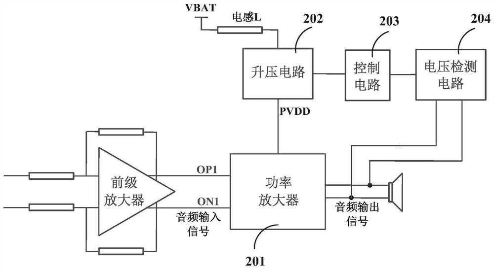
[0030] The present invention proposes a high-efficiency automatic modulation and boosting circuit, please refer to figure 2 , including a power amplifier 201 , a boost circuit 202 , a control circuit 203 and a voltage detection circuit 204 .

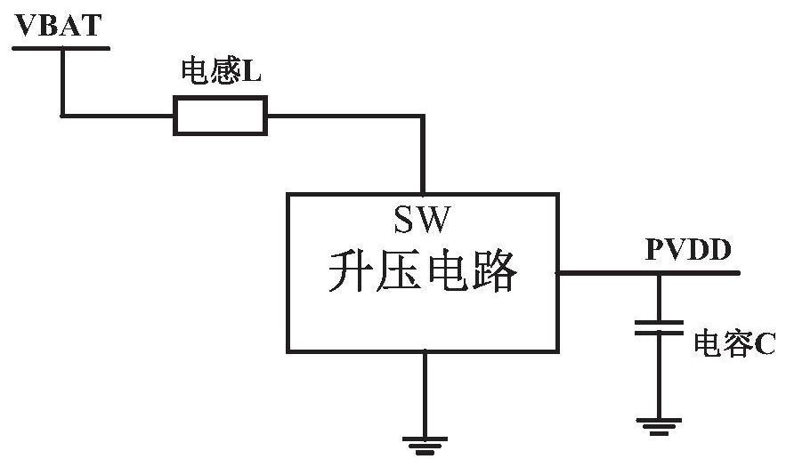
[0031] Specifically, the power amplifier 201 is connected to the boost circuit 202 for amplifying the audio input signal and outputting the audio output signal. The boost circuit 202 is connected to the power amplifier 201 and the control circuit 203 , and is used to convert the power supply voltage VBAT into a high voltage PVDD and supply power to the power amplifier 201 under the control of the control circuit 203 . The voltage detection circuit 204 is connected to the power amplifier 201 and the control circuit 203, and is used to detect the audio output signal and supply it to the control ...


PUM


Abstract

The present invention provides a high-efficiency automatic modulation and boosting circuit and a control method. The circuit includes a power amplifier, a boosting circuit, a control circuit and a voltage detection circuit; the power amplifier is connected to the boosting circuit for converting audio The input signal is amplified and the audio output signal is output; the booster circuit is connected to the power amplifier and the control circuit, and is used to convert the power supply voltage into a high voltage under the control of the control circuit and supply power to the power amplifier The voltage detection circuit is connected to the power amplifier and the control circuit, and is used to detect the audio output signal and supply it to the control circuit; the control circuit is used to control the opening and closing of the boost circuit. The high-efficiency automatic modulation and boosting circuit provided by the invention can achieve the dual goals of high efficiency and high output power, and solves the problem of low efficiency of the existing boosting circuit.

Description

technical field [0001] The invention relates to the technical field of electronic circuits, in particular to a high-efficiency automatic modulation and boosting circuit and a control method. Background technique [0002] In the application of audio amplifier, a higher PVDD output voltage can be generated by a boost converter to achieve higher output power. figure 1 It is a schematic diagram of the circuit structure of a common boost converter. Please refer to figure 1 , the boost converter includes an input voltage VBAT, an energy storage inductor L, a boost circuit, an output capacitor C and an output voltage PVDD. The disadvantage of this boost conversion circuit application is that the efficiency is poor at low output power, because at this time there is an additional set of boost circuit operations. [0003] In order to achieve a higher output power, the existing boost conversion circuit will start the boost circuit to make the output voltage reach the target voltage ...

Claims


Application Information

Patent Timeline
Patent Type & Authority Patents(China)
IPC IPC(8): H04R3/12
CPCH04R3/12H04R2430/00H03F3/187H03F3/45475
Inventor 林其亮江宇晟
Owner 林其亮
Features
  • R&D
  • Intellectual Property
  • Life Sciences
  • Materials
  • Tech Scout
  • Unparalleled Data Quality
  • Higher Quality Content
  • 60% Fewer Hallucinations
Learn More