Mixer used for ventilation air methane and drawing-out methane and having automatic concentration control function

A mixer and gas technology, applied in the direction of mixers, mixing methods, gas and gas/steam mixing, etc., can solve the problems of not being able to adjust the methane concentration, and the mixer cannot meet the mixing requirements of exhaust gas and exhaust air, etc., to achieve Wide range of effects

Pending Publication Date: 2017-11-21
HENAN DIESEL ENGINE IND
6 Cites 0 Cited by

AI-Extracted Technical Summary

Problems solved by technology

[0003] Since the processing capacity of each set of coal mine exhaust air oxidation device is generally tens of thousands of cubic meters per hour, the existing mixer cannot meet the mixing requirements of exhaust gas and exhaust air; with the research and application of coal mine exhaust air oxidation device, although There are some mixers for mixing exhaust gas and exhaust gas, but there is no exhaust gas and exhaust gas mixer with automatic concentration control function
Existing patents "Mixer for Coal Mine Drainage Gas and Ventilation Gas" (Application No.: CN 201020519416.1) and "A Self-priming Swirling Coal Mine Dr...

Abstract

The invention relates to a mixer used for ventilation air methane and drawing-out methane and having an automatic concentration control function, belonging to the field of gas supplying technology for oxidation apparatuses of coal mine ventilation air methane. The mixer provided by the invention has a cylindrical shell; two ends of the shell are a ventilation air methane inlet end and a mixed gas outlet end, respectively; the excircle surface of the shell is provided with a plurality of drawing-out methane inlet pipes; the ventilation air methane inlet end of the shell is provided with a transition pipe with increasingly decreasing diameters; the transition pipe is connected with the shell via casting or welding; the tail end surface of the transition pipe is located at one side, close to the ventilation air methane inlet end, of the axis of each of the drawing-out methane inlet pipes; the shell is also internally provided with a valve core capable of moving along the axis of the shell; a gas inlet gap is formed between one end surface of the valve core and the end surface, close to the ventilation air methane inlet end, of the transition pipe, and the other end of the valve core is fixedly connected with a driving mechanism driving the valve core to move; and the mixer is further provided with a gas flow valve body. The mixer provided by the invention realizes uniform mixing of large-flow ventilation air methane and drawing-out methane and has a wide application scope.

Application Domain

Transportation and packagingMixer accessories +2

Technology Topic

Automatic controlControl function +8

Image

  • Mixer used for ventilation air methane and drawing-out methane and having automatic concentration control function
  • Mixer used for ventilation air methane and drawing-out methane and having automatic concentration control function
  • Mixer used for ventilation air methane and drawing-out methane and having automatic concentration control function

Examples

  • Experimental program(1)

Example Embodiment

[0017] The present invention will be described with reference to the drawings and specific embodiments:
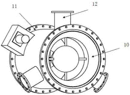
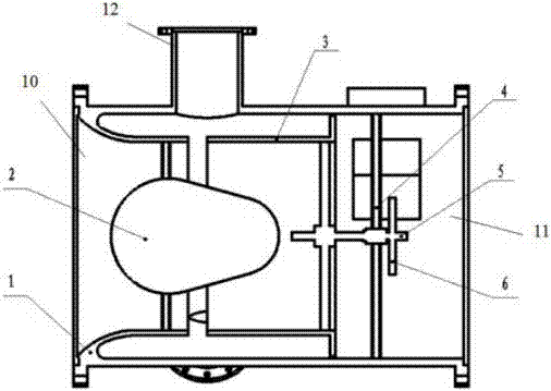
[0018] Such as figure 1 , figure 2 As shown, an exhaust air and exhaust gas mixer with automatic concentration control function, the mixer has a cylindrical shell 1; the two ends of the shell 1 are the exhaust air inlet end 10 and The mixed gas outlet end 11; the exhaust air inlet end 10 and the mixed gas outlet end 11 are provided with flanges and connected with corresponding pipes; the outer circumferential surface of the shell 1 has a plurality of exhausted gas uniformly distributed along the circumference Inlet pipe 12; the axis of the suction gas inlet pipe 12 is perpendicular to the axis of the casing 1; the number of the suction gas inlet pipes is 2-3 to ensure that the exhaust gas can evenly enter the mixer; The exhaust air inlet end 10 of the casing 1 is provided with a transition pipe with a tapered diameter. The transition pipe and the casing are connected by casting or welding. The end surface of the transition pipe is located near the exhaust air inlet end of the exhaust gas inlet pipe axis. One side; the outer side of the mixed gas outlet end 11 of the shell 1 is provided with a stepping motor mounting support, which is connected with the shell by casting or welding; the shell 1 is also provided with an inner edge Spool 3 with axis movement; combined Figure 4 , Figure 5 , The valve core 3 has a cylindrical structure, the inner diameter of the valve core 3 is the same as the inner diameter of the transition pipe, and the outer surface of the valve core 3 has a plurality of protruding guide rails 14 on the inner wall of the housing 1 There is a guide groove that matches with the guide rail on the outer surface of the valve core; there is an air inlet gap between one end surface of the valve core 3 and one end surface of the transition pipe near the exhaust air inlet end for draining gas into the mixer , And the other end of the valve core 3 is fixedly connected with the driving mechanism that drives its action; combined image 3 , The driving mechanism includes a transmission screw 5, a transmission wheel 6, a driving wheel 7 and a stepping motor 9; the stepping motor 9 is fixed on the mounting support outside the mixed gas outlet end, and the axis of the stepping motor 9 Depending on the form of the intermediate transmission, it can be arranged parallel or perpendicular to the axis of the housing 1; one end of the transmission screw 5 is threadedly fitted with the valve core 3, and the other end is fixedly connected to the transmission wheel 6. The driving wheel 7 and the stepping motor 9 are connected by a coupling 8, and the driving wheel 7 and the driving wheel 6 are connected by gear matching or a transmission belt; the driving wheel 6 is connected to the driving wheel at the output end of the stepping motor. The wheel 7 cooperates to drive the transmission screw 5 to rotate, thereby driving the valve core 3 to move along the axis of the casing in the housing 1, adjust the gap between the valve core 3 and the transition pipe, and further adjust the gas drainage Enter the gap of the mixer to achieve the purpose of adjusting the concentration of the mixer; the mixer is also provided with an air flow valve body 2 for adjusting the flow rate of the mixed gas of exhaust air and exhaust gas entering the shell; the air flow valve body 2 One end is fixed in the transition pipe by a bracket, the other end passes through the transition pipe, and the gap between the transition pipe and the valve core is located in the valve core 3; the air flow valve body 2 is formed by one side of the transition pipe Hollow drop shape with a diameter tapering to the spool side.
[0019] The outlet end of the mixed gas is connected with the outlet pipe of the mixer; a gas concentration sensor is arranged on the outlet pipe of the mixer.
[0020] The method of closed-loop control of the mixed gas concentration by the above-mentioned exhaust air and exhaust gas mixer: the gas concentration sensor set on the mixed gas outlet pipe sends the collected concentration signal to the controller, and the controller sends the collected concentration signal and setting The mixed gas concentration signal is compared, and then the control signal is output to the stepping motor. The stepping motor drives the driving wheel to realize forward and reverse rotation according to the control signal, so as to adjust the size of the exhaust gas inlet gap, thereby controlling the amount of exhaust gas entering the mixer Size; real-time measurement of mixed gas methane concentration signal to achieve closed-loop control of mixed gas concentration.

PUM

no PUM

Description & Claims & Application Information

We can also present the details of the Description, Claims and Application information to help users get a comprehensive understanding of the technical details of the patent, such as background art, summary of invention, brief description of drawings, description of embodiments, and other original content. On the other hand, users can also determine the specific scope of protection of the technology through the list of claims; as well as understand the changes in the life cycle of the technology with the presentation of the patent timeline. Login to view more.

Similar technology patents

Jet preparation device of amorphous alloy strip and preparation method thereof

ActiveCN104493116ALarge span of thicknessWide range of applications
Owner:江西中磁科技协同创新有限公司

Classification and recommendation of technical efficacy words

Why Eureka
Try Eureka