Low-temperature operation prevention automatic protecting method and control system for flue gas denitrification catalyst

A technology of denitrification catalyst and control system, applied in the field of automatic protection method and control system of flue gas denitrification catalyst against low temperature operation, which can solve the problems of high cost, low ultra-high temperature operation, damage of denitrification catalyst, etc., and achieve temperature and time control Accurate, automatic control is accurate, and it is not easy to control the effect of deviation

Active Publication Date: 2017-11-24
TIANJIN DATANG INT PANSHAN POWER GENERATION +1
View PDF8 Cites 5 Cited by
  • Summary
  • Abstract
  • Description
  • Claims
  • Application Information

AI Technical Summary

Problems solved by technology

In addition, once the denitration catalyst is poisoned and fails, the cost of active regeneration or replacement of a new denitration catalyst will be extremely expensive, which will also affect the economic benefits of the enterprise
In summary, if the activity of the denitrification catalyst in the flue gas SCR process denitrification system is reduced or even eventually poisoned and fails, it will have adverse effects on the operation, safety and environmental protection of the entire enterprise, especially the environmental protection will have a greater impact on the entire society. In actual operation, ultra-low temperature operation is prone to occur, and the probability of ultra-high temperature operation is relatively small. Therefore, how to protect the denitrification catalyst against low temperature operation is an important research topic in the flue gas SCR process denitrification technology
[0004] In order to protect the activity of the denitrification catalyst and improve the efficiency of flue gas

Method used


Image

  • Low-temperature operation prevention automatic protecting method and control system for flue gas denitrification catalyst
  • Low-temperature operation prevention automatic protecting method and control system for flue gas denitrification catalyst

Examples


Example Embodiment

[0046] Example one:

[0047] Such as Figure 1-2 As shown, an automatic protection method for flue gas denitration catalyst against low temperature operation includes:

[0048] S1, pre-set the following critical temperature in the DCS control system:

[0049] Maximum operating temperature MXOT: the highest flue gas temperature that deactivates the denitration catalyst;

[0050] Recovery temperature RT: the lowest flue gas temperature to regenerate the denitration catalyst;

[0051] Minimum operating temperature MOT: the lowest flue gas temperature at which the denitration catalyst is deactivated;

[0052] Minimum ammonia injection temperature MIT: the minimum flue gas temperature for ammonia injection by the denitrification catalytic device;

[0053] Low temperature operation longest time t2: the longest time allowed for denitrification catalyst to operate within MIT

[0054] Critical t1: The t1 is the shortest regeneration time required to regenerate the denitration catalyst at th...

Example Embodiment

[0067] Embodiment two:

[0068] Such as Figure 1-2 As shown, as V2O5 / TiO2 as a denitration catalyst, it is used in the denitration catalyst device of the present invention.

[0069] An automatic protection method for flue gas denitration catalyst against low-temperature operation, including:

[0070] S1, pre-set the following critical temperature in the DCS control system:

[0071] Maximum operating temperature MXOT: The maximum flue gas temperature that deactivates the denitration catalyst is 420℃;

[0072] Recovery temperature RT: The lowest flue gas temperature for regeneration of the denitration catalyst is 310℃;

[0073] Minimum operating temperature MOT: The minimum flue gas temperature to deactivate the denitration catalyst is 300℃;

[0074] Minimum ammonia injection temperature MIT: The minimum flue gas temperature for ammonia injection by the denitration catalytic device is 290℃;

[0075] Maximum low temperature operation time t2: The maximum time allowed for the denitrification...

Example Embodiment

[0087] Example three:

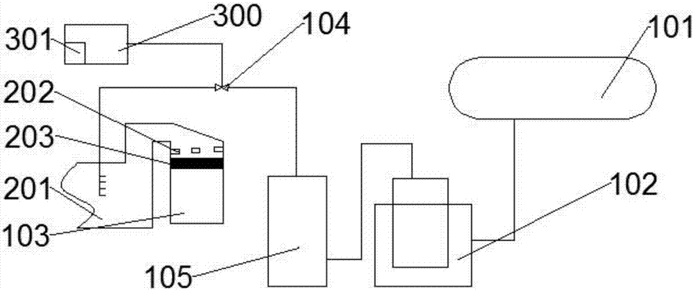
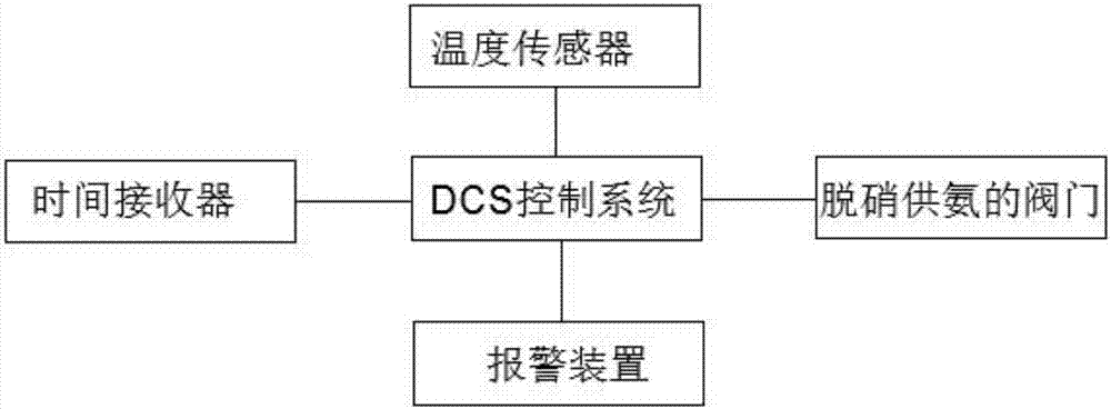
[0088] Such as figure 1 As shown, an automatic protection system applying the automatic protection method for low-temperature operation of the flue gas denitration catalyst includes a DCS control system 300, an ammonia supply system, and a denitration device 103. The denitration device 103 is provided with a flue 201, and the flue gas flows along the flue gas. The duct 201 enters the denitrification device 103, the flue 201 is connected with the ammonia supply system through the ammonia supply pipeline, the ammonia supply pipeline is provided with a valve 104, the denitration device 103 is equipped with a temperature sensor 202, the temperature sensor 202 and the DCS control system 300 Electrically connected, the DCS control system 300 is connected to the valve 104.

[0089] The ammonia supply system includes a liquid ammonia storage tank 101, an evaporation tank 102, and a buffer tank 105. The liquid ammonia in the liquid ammonia storage tank 101 passes thr...


PUM


Abstract

The invention belongs to the technical field of flue gas denitrification and relates to a low-temperature operation prevention automatic protecting method and control system for a flue gas denitrification catalyst. The low-temperature operation prevention automatic protecting method for the flue gas denitrification catalyst comprises the steps that S1, the critical temperature (please refer to the specification) is preset in a distribution control system (DCS); S2, a temperature sensor detects the flue gas temperature Q in a flue in real time and has an access to the DCS; S3, the DCS counts up the continuous operation time A of the condition of MIT<Q<MOT and the continuous operation time B of the condition of RT<Q<MXOT; and S4, the DCS controls a valve of a denitrification and ammonia supply pipeline and a timer by referring to the continuous operation time A, the continuous operation time B, the flue gas Q and the critical temperature. By means of the control method, control automation can be achieved, the temperature and time are controlled more accurately, and the denitrification catalyst is prevented from being irreversibly damaged by manual control deviation.

Description

technical field [0001] The invention belongs to the technical field of flue gas denitrification, and in particular relates to an automatic protection method and a control system for a flue gas denitrification catalyst against low-temperature operation. Background technique [0002] Nitrogen oxide (NOx) is one of the main air pollutants, which will promote the formation of acid rain, increase the concentration of ozone in the near-surface atmosphere, produce photochemical smog, and affect air visibility; it has a strong stimulating effect on the human body, causing respiratory diseases, serious will result in death. [0003] The main source of nitrogen oxides in industrial production is the combustion of fuel. The combustion of fuel is mainly the combustion of coal. The temperature required for the chemical reaction of SCR denitration process mainly depends on the type of denitration catalyst. When the flue gas temperature is lower than the lower limit of the applicable temp...

Claims


Application Information

Patent Timeline
IPC IPC(8): B01D53/86B01D53/88B01D53/90B01D53/56
CPCB01D53/8631B01D53/8696B01D53/88B01D53/90B01D2258/0283
Inventor 邢希东
Owner TIANJIN DATANG INT PANSHAN POWER GENERATION
Why Eureka
Try Eureka