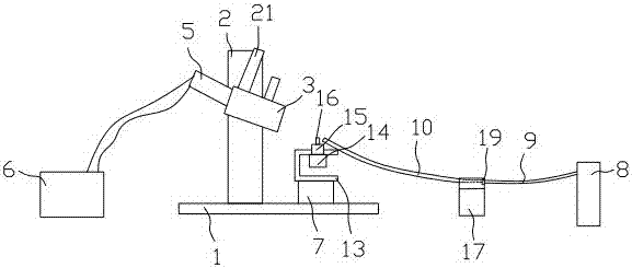
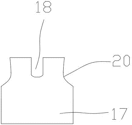
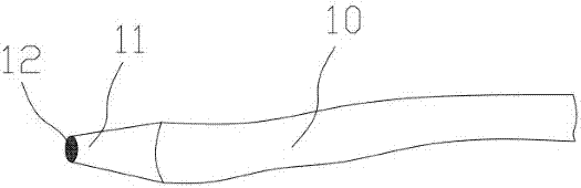
[0011] A laser welding machine such as Figure 1 to Figure 5 As shown, it includes a base 1, a mounting bracket 2 is provided on the base 1, a laser emitting head 3 is installed on the mounting bracket 2, and a monitor 5 for monitoring the welding process of the cladding 4 is connected to the laser emitting head 3. The monitor 5 is connected with the display 6 circuit, and a cladding fixture that drives the cladding 4 to rotate relative to the laser emitting head 3 is provided on one side of the laser emitting head 3, and the bottom of the cladding fixture is provided with a driving cladding fixture to lift and translate. The mobile module 7, the mobile module 7 is installed on the base 1, and the base 1 is also provided with an argon cylinder 8, the argon cylinder 8 is connected with the argon gas outlet pipe 9, and the argon gas outlet pipe 9 is connected with the bamboo tube. 10 is connected, a nozzle 11 is arranged on the free end of the bamboo tube 10, and a wire mesh 12 is wrapped on the nozzle 11 of the bamboo tube 10. The laser welding spot on the opposite. The bamboo tube 10 may also be called a universal bamboo tube or a universal tube or a universal cooling tube. The moving module 7 can realize the functions of lifting and translation, which is the prior art. For example, the translation function can be realized by the cooperation of the screw and the screw seat or the cooperation of the gear and the rack, and the lifting function can also be realized by It is the prior art to integrate the transmission structure with the translation function and the transmission structure with the lifting function into the same module by cooperating with the screw base or the cylinder to realize the lifting function.
[0012] The cladding fixture includes a U-shaped mounting seat 13, one side wall of the mounting seat 13 is fixed on the moving module 7, the drive motor 14 is mounted on the inner wall surface of the other side wall of the mounting seat 13, and drives the The output shaft of the motor 14 vertically penetrates the side wall of the mounting seat 13 and is fixedly connected with the clamping copper seat 15. The upper surface of the clamping copper seat 15 is provided with a clamping hole. The lower part of the holding hole has a horizontally arranged heat dissipation hole that penetrates the side wall of the clamping copper base 15. When the encapsulation 4 needs to be welded, insert the encapsulation 4 into the clamping hole on the upper surface of the clamping copper base 15. Due to the depth of the clamping hole It is smaller than the length of the cladding shell 4, so the cladding shell 4 is partially exposed beyond the clamping hole on the clamping copper seat 15, which is convenient for welding and sealing. The driving motor 14 drives the clamping copper seat 15 to rotate, thereby driving the cladding shell 4 to rotate. , so that the cladding 4 can be effectively welded and sealed, and a horizontal heat dissipation hole penetrating the side wall of the clamping copper base 15 is arranged at the lower part of the clamping hole to speed up the dissipation of the heat generated during the welding process.
[0013] The upper surface of the clamping copper base 15 is provided with a boss 16 whose size is smaller than that of the clamping copper base 15 , and a clamping hole is arranged on the upper surface of the boss 16 . It can be rotated more smoothly, and the size of the boss 16 is smaller than the size of the clamping copper seat 15, so that the nozzle 11 can be closer to the cladding 4, which improves the quality of welding and sealing, and avoids welding black spots.
[0014] The nozzle 11 is in the shape of a cone or a flat horn, the large end of the nozzle 11 is connected to the bamboo tube 10, and the small end is opposite to the laser welding point emitted by the laser emitting head 3 on the cladding 4, and the wire mesh 12 is wrapped in On the small end of the nozzle 11, since the nozzle 11 is in the shape of a cone or a flat horn, the size of the nozzle 11 gradually changes from large to small. Therefore, when the argon gas flows from the large end of the nozzle 11 to the small end, the gas The cross-sectional area that passes through gradually becomes smaller, which can make the ejected gas stronger. Combined with the wire mesh 12 wrapped at one end of the small head, the gas with higher ejection strikes the wire mesh 12 to disperse the gas evenly, thereby The gas ejected from the nozzle 11 can evenly cover the laser welding points on the cladding 4, effectively avoiding welding black spots on the cladding 4, and improving the welding quality of the cladding 4; especially when the nozzle 11 is in the shape of a flat horn , the jetted airflow is stronger, therefore, it is easier to be dispersed evenly when it hits the wire mesh 12 , and it is more effective to ensure that the jetted argon can evenly cover the laser welding points on the cladding 4 .
[0015] The height of the small end of the flat horn-shaped nozzle 11 is the same as the height of the part of the cladding 4 exposed to the outside of the clamping hole of the boss 16, which is more conducive to the sprayed argon gas to cover the air on the cladding 4. Laser welding spots.
[0016] The connection between the bamboo tube 10 and the argon gas outlet tube 9 is provided with a fixing seat 17 for fixing the bamboo tube 10. The upper surface of the fixing seat 17 is provided with an arc-shaped groove 18. The free end is connected with a threaded connector 19 with a threaded hole, the side surface of the threaded connector 19 is in a polygonal structure, the end of the bamboo tube 10 with a screw is screwed into the threaded hole of the threaded connector 19, Fasten the bamboo tube 10 and the threaded connector 19 into one, and insert the connecting part of the threaded connector 19 and the bamboo tube 10 into the arc groove 18 on the fixing seat 17, so that the side surface of the threaded connector 19 is The side walls of the arc-shaped groove 18 on the fixed seat 17 form surface contact, thereby increasing the contact area between the threaded connector 19 and the arc-shaped groove of the fixed seat 17, increasing the friction force, and making the bamboo tube 10 stuck in the fixed position. The arc-shaped groove of the seat 17 is more stable, and in combination with the weight of the fixing seat 17 itself, the vibration of the bamboo tube 10 due to the large airflow during the argon injection can be effectively avoided, thereby preventing the bamboo tube 10 from being damaged by vibration. Deviating from the preset position further ensures that the argon gas ejected from the bamboo tube 10 can cover the laser welding points on the cladding shell 4 , thereby ensuring the welding and sealing quality of the cladding shell 4 .
[0017] The upper parts of the two side walls of the fixing base 17 parallel to the arc-shaped grooves 18 on the fixing base 17 are respectively provided with concave arc surfaces 20 to reduce the weight of the upper part of the fixing base 17 and increase the stability of the fixing base 17 .
[0018] The laser emitting head 3 is also provided with an observation mirror 21 , which is convenient for the staff to observe the working condition of the laser emitting head 3 .
[0019] The mesh number of the wire mesh 12 is 400 meshes, which can disperse the argon gas more finely and uniformly.