
Liquid crystal phase shift unit for reflected adjustable phase shifter

A phase shifter, reflective technology, applied in electrical components, waveguide devices, circuits, etc., can solve the problems of liquid crystal molecules not completely rotated, phase curve and device test value errors, and values ​​not reaching the ideal value, etc. The effect of improving the electrode loading method, simple main structure and improving the degree of orientation

Active Publication Date: 2017-11-24
HEFEI UNIV OF TECH
View PDF1 Cites 54 Cited by
  • Summary
  • Abstract
  • Description
  • Claims
  • Application Information

AI Technical Summary

Problems solved by technology

However, the conductive patch electrodes constituting the resonant unit cannot completely cover the surface of the unit, resulting in the inability of the bias electric field to be evenly distributed on the patch unit.
The electrostatic field and RF field after electrification will have three vector components, which will have two effects: on the one hand, because the liquid crystal molecules cannot be uniformly oriented, the liquid crystal material will have inhomogeneity; on the other hand, it will increase The effect of liquid crystal anisotropy
Since the electric field cannot be uniformly distributed in the entire space of the liquid crystal cell, there is a large error between the phase curve obtained by the simulation calculation and the device test value, and some liquid crystal molecules cannot be completely rotated, ε / / The value does not meet the ideal value

Method used


Image

  • Liquid crystal phase shift unit for reflected adjustable phase shifter
  • Liquid crystal phase shift unit for reflected adjustable phase shifter
  • Liquid crystal phase shift unit for reflected adjustable phase shifter

Examples


Embodiment Construction

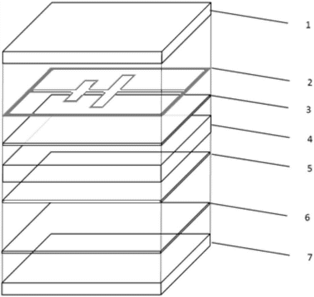
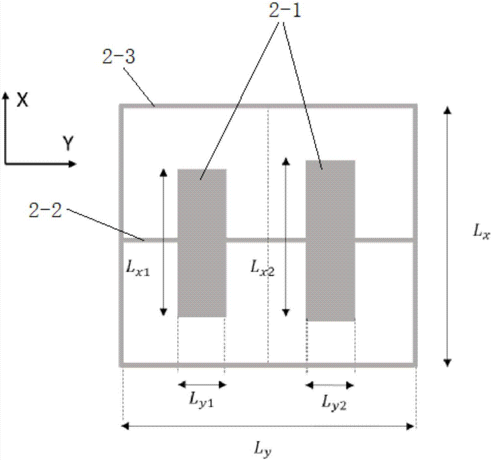
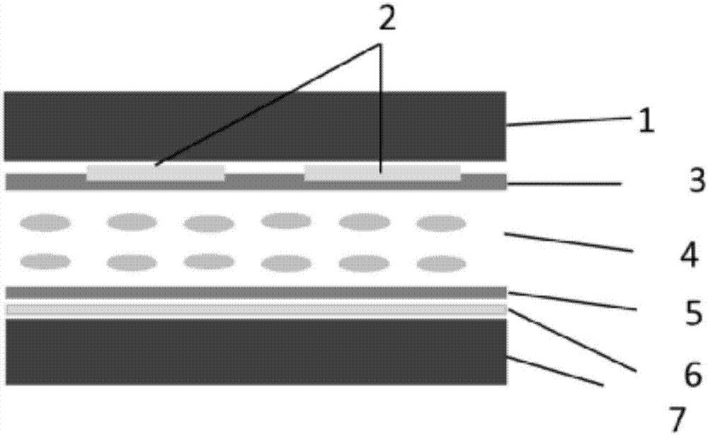
[0018] Such as figure 1 , 2 . As shown in 3, a liquid crystal phase shifting unit for a reflective adjustable phase shifter includes upper and lower two-layer dielectric substrates 1, 7, and the gap between the upper and lower two-layer dielectric substrates 1, 7 is injected with The liquid crystal layer 4, the metal microstrip patch electrode 2 is provided on the lower side of the upper dielectric substrate 1, the metal total reflection ground electrode 6 is provided on the upper side of the lower dielectric substrate 7, and the upper and lower surfaces of the liquid crystal layer 4 are respectively provided with polyamide Imine film coatings 3, 5; the metal microstrip patch electrode 2 includes two identical dipole patches 2-1, a bias voltage loading line 2-2, auxiliary electrodes 2-3, two Two dipole patches 2-1 are arranged in parallel, and the bias voltage loading line 2-2 is orthogonally connected to two dipole patches 2-1 to form a patch unit. The auxiliary electrode 2-...


PUM


Abstract

The invention discloses a liquid crystal phase shift unit for a reflected adjustable phase shifter. The liquid crystal phase shift unit comprises two upper and lower layers of medium substrates, a liquid crystal layer is injected in the gap between the two upper and lower layers of medium substrates, a metal microstrip patch electrode is arranged on the lower side of the upper layer medium substrate, a metal total reflection ground electrode is arranged on the upper side of the lower layer medium substrate, and polyimide film coating is respectively arranged on upper and lower surfaces of the liquid crystal layer; the metal microstrip patch electrode comprises two identical dipole patches, an offset voltage loading line and an auxiliary electrode, the two dipole patches are arranged in parallel, the offset voltage loading line is connected with the two dipole patches orthogonally to form a patch unit, the auxiliary electrode is a quadrilateral metal frame, and the quadrilateral metal frame surrounds the whole patch unit and is connected with the offset voltage loading line. The auxiliary electrode has a simple main body structure, educes the saturation bias voltage, and can be used in the field of liquid crystal reflected phase shifters and phase control antennas within microwave, millimeter wave and terahertz frequency bands.

Description

technical field [0001] The invention belongs to the technical field of reflective phase shifters and phase-controlled antennas in the technical fields of microwave, millimeter wave and terahertz, and in particular relates to a liquid crystal phase shifter used for reflective adjustable phase shifters. Background technique [0002] The reflective adjustable phase shifter uses the adjustable dielectric constant of the liquid crystal to realize the control of the phase of the reflected electromagnetic wave by the microstrip circuit. It can be used to realize a reconfigurable reflectarray antenna, a phased array reflectarray antenna based on liquid crystal materials It not only has the advantages of high gain, strong directivity, small size and light weight of the microstrip reflectarray antenna, but also can realize electronically controlled continuous scanning of the antenna beam. [0003] At present, the research on liquid crystal microwave devices generally regards liquid cr...

Claims


Application Information

Patent Timeline
IPC IPC(8): H01P1/18
CPCH01P1/18H01P1/184
Inventor 杨军夏天雨杨阳尹治平邓光晟陆红波
Owner HEFEI UNIV OF TECH
Learn More