Non-local-oscillator low-phase-noise microwave signal optical frequency-doubling generation device and method

A microwave signal and optical frequency doubling technology, which is applied in electromagnetic wave transmission systems, electromagnetic network arrangements, ring electromagnetic networks, etc., can solve the problem of difficulty in balancing the frequency multiplication factor and frequency tunable range, and achieve excellent phase noise performance and large frequency Range tunable to improve the effect of frequency range

Active Publication Date: 2017-11-24
EAST CHINA NORMAL UNIV
View PDF4 Cites 19 Cited by
  • Summary
  • Abstract
  • Description
  • Claims
  • Application Information

AI Technical Summary

Problems solved by technology

[0006] The purpose of the present invention is to solve the problem that it is difficult to balance the frequency multiplication factor and the frequency tunable range in the microwave signal generation method of the photoelectric oscillator in the background technology. The present invention proposes a microwave signal with a large frequency range, no local oscillator, and low phase noi

Method used


Image

  • Non-local-oscillator low-phase-noise microwave signal optical frequency-doubling generation device and method
  • Non-local-oscillator low-phase-noise microwave signal optical frequency-doubling generation device and method
  • Non-local-oscillator low-phase-noise microwave signal optical frequency-doubling generation device and method

Examples


Embodiment 1

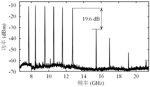
[0058]In this embodiment, the bandwidth of the PS-FBG reflection spectrum is 50GHz, the position of the extremely narrow depression on the reflection spectrum is 1549.99nm, and the bandwidth is 40MHz. increase to generate resonant signals of different frequencies. The half-wave voltage of the DP-QPSK modulator is 3.5V. The polarization controller is adjusted so that the directions of the two main axes of the polarization beam splitter and the directions of the two main axes of the DP-QPSK modulator are respectively consistent. The two sub-DP-MZMs of the DP-QPSK modulator are set as follows: the two sub-MZMs of the sub-DP-MZM constituting the optoelectronic oscillator loop are respectively biased at the maximum transmission point and the minimum transmission point, and the main MZM is biased at the orthogonal point , in another sub-DP-MZM, the sub-MZM of the input RF signal is biased at the minimum transmission point, and the sub-MZM without input sets the bias voltage so that...

Embodiment 2

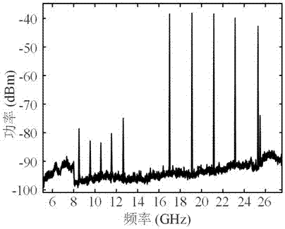
[0060] In this embodiment, the bandwidth of the PS-FBG reflection spectrum is 50GHz, the position of the extremely narrow depression on the reflection spectrum is 1549.99nm, and the bandwidth is 40MHz. increase to generate resonant signals of different frequencies. The half-wave voltage of the DP-QPSK modulator is 3.5V. The polarization controller is adjusted so that the directions of the two main axes of the polarization beam splitter and the directions of the two main axes of the DP-QPSK modulator are respectively consistent. The two sub-DP-MZMs of the DP-QPSK modulator are set as follows: the two sub-MZMs of the sub-DP-MZM constituting the optoelectronic oscillator loop are respectively biased at the maximum transmission point and the minimum transmission point, and the main MZM is biased at the orthogonal point , in another sub-DP-MZM, the sub-MZM of the input RF signal is biased at the maximum transmission point, and the sub-MZM without input sets the bias voltage so tha...


PUM


Abstract

The invention discloses a non-local-oscillator low-phase-noise microwave signal optical frequency-doubling generation device and method, and belongs to the technical field of microwave signal generation. According to the device and the method, a narrow-band microwave photonic filter is formed by utilizing an equivalent phase modulation characteristic of one double parallel Mach-Zehnder modulator (DP-MZM) integrated in a polarized multiplexed double parallel Mach-Zehnder modulator (DP-QPSK modulator) and a phase shifting fiber bragg grating (PS-FBG); and in an optoelectronic oscillator, generation of a frequency tunable low-phase-noise microwave resonance signal is implemented. Signal frequency doubling of the generated microwave resonance signal is implemented by the other DP-MZM integrated in the DP-QPSK modulator so as to generate a high-frequency microwave signal. The non-local-oscillator low-phase-noise microwave signal optical frequency-doubling generation device and method disclosed by the invention can overcome the defect of limitation of the electronic bottleneck of an electronic system in the aspect of generating the high-frequency low-phase-noise microwave signal, and implement generation of the low-phase-noise microwave signal with a magnitude of dozens of GHz and even hundreds of GHz.

Description

technical field [0001] The invention relates to the technical field of microwave signal generation, in particular to a device and method for generating an optical frequency multiplication of a microwave signal with a large frequency range and no local oscillator and low phase noise. Background technique [0002] With the continuous development of wireless communication, radar and other technologies, people's requirements for wireless communication speed are getting higher and higher, and the requirements for radar imaging resolution are also increasing, which will inevitably promote the demand for wireless spectrum resources in communication, radar and other technologies From the low frequency band to the higher frequency band. For example, wireless communication technology in the 60GHz frequency band is becoming a popular technology for broadband access due to its high access rate and no need to apply for additional licenses. Millimeter wave radar technology has received mo...

Claims


Application Information

Patent Timeline
IPC IPC(8): H04B10/275H04B10/291H04B10/50H04B10/516H04B10/556H04B10/572
CPCH04B10/275H04B10/2912H04B10/503H04B10/516H04B10/5561H04B10/572
Inventor 陈阳
Owner EAST CHINA NORMAL UNIV
Why Eureka
Try Eureka