Slurry fixing device of hydraulic slurry cutting machine and hydraulic slurry cutting machine

A technology of fixing device and cutting machine, which is applied in the field of papermaking machinery, can solve the problems of cumbersome pulp cutting, high friction force of cutter, high labor intensity, etc., achieve good promotion and use value, reduce running resistance, and reduce labor intensity Effect

Inactive Publication Date: 2017-11-28
山东天和纸业有限公司
View PDF9 Cites 1 Cited by
  • Summary
  • Abstract
  • Description
  • Claims
  • Application Information

AI Technical Summary

Problems solved by technology

[0004] The technical task of the present invention is to provide a slurry fixing device and a hydraulic slurry cutting machine for the above deficiencies, which can solve the problems of cumbersome slurry cutting in the prior art, high labor intensity, and black spots on the slurry cutting surface. The fiber is carbonized, and the slurry cannot be fixed when cutting, and the guide mechanism of the cutter produces a large friction force.

Method used


Image

  • Slurry fixing device of hydraulic slurry cutting machine and hydraulic slurry cutting machine
  • Slurry fixing device of hydraulic slurry cutting machine and hydraulic slurry cutting machine

Examples


Embodiment 1

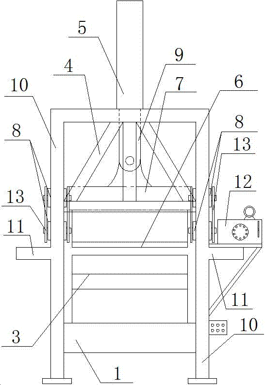
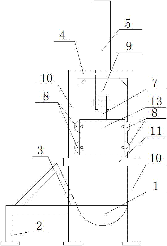
[0027] The slurry fixing device of the hydraulic slurry cutting machine of the present invention, the slurry fixing device includes a workbench 1, a feeding platform 2 and a slurry retaining frame 3, and the workbench 1 is fixed at the lower center of the hydraulic slurry cutting machine; The workbench 1 is a workbench 1 with a semicircular arc structure with an upper opening; the feeding platform 2 of the L-shaped structure is arranged at the inlet of the workbench 1, and the upper surface of the feeding platform 2 is arranged parallel to the ground, and the triangular structure can be The movable slurry stop frame 3 is set on the feeding platform 2; the upper surface of the feeding port of the working table 1 and the upper surface of the feeding platform 2 are set on the same plane, and the working table 1 and the feeding platform 2 are fixed by welding connected.

Embodiment 2

[0029] The hydraulic slurry cutting machine of the present invention includes a frame 4, the upper end of the frame 4 is provided with a hydraulic cylinder 5, the middle part of the frame 4 is provided with a transmission connection device, the lower part of the transmission connection device is connected with the cutter 6, and the lower end of the frame 4 A slurry fixing device is provided; the slurry fixing device is a slurry fixing device of any hydraulic slurry cutting machine in embodiment 1; the slurry fixing device is arranged at the bottom of the hydraulic slurry cutting machine; the transmission connection device includes a connecting Bracket 7 and guide wheel 8, the top of connecting bracket 7 of fan-shaped structure is connected with the piston rod 9 of hydraulic cylinder 5 by hinge; Connected to the inside of each column 10 of the frame 4; the connecting bracket 7 includes a guide wheel support plate 13, the guide wheel support plate 13 is located at the two ends of...


PUM


Abstract

The invention discloses a slurry fixing device of a hydraulic slurry cutting machine and the hydraulic slurry cutting machine, belongs to the technical field of paper manufacturing machinery, and aims to solve the technical problems that in the prior art, the slurry cutting is tedious and the labor intensity is high; the slurry cutting surface is prone to turning black and the fiber carbonization is caused; as well as slurry cannot be fixed when being cut, and the relatively great friction force is generated by a guiding mechanism of a cutter. According the adopted technical scheme, the slurry fixing device comprises a workbench, a loading platform and a slurry baffle frame, wherein the workbench is fixedly arranged at the central position of the lower part of the hydraulic slurry cutting machine, and adopts a semi-circular-arc structure of which the upper part is open; the loading platform is arranged at the feed inlet of the workbench; and the slurry baffle frame is arranged on the loading platform. By adoption of the slurry fixing device, the coiled slurry can be quickly cut; in the cutting process, the slurry can be steadily fixed; the slurry cutting surface can be prevented from turning black; the labor intensity of production can be reduced; and the operation efficiency can be improved.

Description

technical field [0001] The invention relates to the technical field of papermaking machinery, in particular to a slurry fixing device of a hydraulic slurry cutting machine and a hydraulic slurry cutting machine. Background technique [0002] With the development of the modern mechanical processing industry, the requirements for cutting quality and precision are constantly improving, and the requirements for improving production efficiency, reducing production costs, and highly intelligent automatic cutting functions are also increasing. Due to the different application fields of cutting machines, the types of cutting machines are also different. Cutting machines can be divided into hydraulic cutting machines, flame cutting machines, plasma cutting machines, laser cutting machines and water cutting machines. For example: the laser cutting machine has the fastest efficiency, the highest cutting precision, and the cutting thickness is generally small; the plasma cutting machin...

Claims


Application Information

Patent Timeline
Patent Type & Authority Applications(China)
IPC IPC(8): B26D1/08B26D5/12B26D7/01B26D7/00
CPCB26D1/08B26D5/12B26D7/0006B26D7/01B26D2007/013
Inventor 宁方桥
Owner 山东天和纸业有限公司
Why Eureka
Try Eureka