Thermal infrared image stitching method

An infrared image and thermal infrared technology, which is applied in the field of image processing, can solve the problems of blurred targets, affecting the imaging quality of thermal infrared images, and low resolution, and achieve the effect of improving feasibility and correctness

Active Publication Date: 2017-11-28
INST OF DEFENSE ENG ACADEMY OF MILITARY SCI PLA CHINA
View PDF7 Cites 10 Cited by
  • Summary
  • Abstract
  • Description
  • Claims
  • Application Information

AI Technical Summary

Problems solved by technology

Due to the special imaging mechanism of thermal infrared radiation, compared with visible light images, thermal infrared images generally have the characteristics of less image informati

Method used


Image

  • Thermal infrared image stitching method
  • Thermal infrared image stitching method
  • Thermal infrared image stitching method

Examples


Embodiment Construction

[0036] In order to make the purpose, technical solution and advantages of the present invention clearer, the technical solution of the present invention will be described in detail below. Apparently, the described embodiments are only some of the embodiments of the present invention, but not all of them. Based on the embodiments of the present invention, all other implementations obtained by persons of ordinary skill in the art without making creative efforts fall within the protection scope of the present invention.

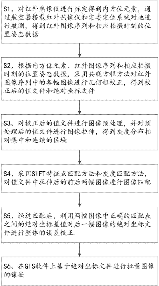
[0037] Such as figure 1 As shown, the present invention provides a kind of splicing method of thermal infrared image, and it comprises the following steps:

[0038] S1. Calibrate the thermal imaging camera to obtain the inner orientation elements, carry out aerial surveys on the ground through the infrared thermal imaging camera and the attitude determination and positioning system carried by the aircraft, and obtain the infrared image sequence and the position...


PUM


Abstract

The invention relates to a thermal infrared image stitching method, which comprises the following steps that: calibrating an infrared thermal imager to obtain an inner orientation element, and carrying out aerial survey on ground through the aircraft carried infrared thermal imager and a positioning and orientation system to obtain an infrared image sequence and position gesture data; according to the inner orientation element, the infrared image sequence and the position gesture data at a corresponding photographing moment, adopting a collinearity equation method to carry out geometric coarse correction on each image in the infrared image sequence to obtain a value file and an absolute coordinate file; carrying out image preprocessing on the value file to carry out image stretching to obtain an area of which the gray level distribution is relatively centralized and continuous; adopting an SIFT (Scale-Invariant Feature Transform) feature point matching method and a gray level distribution method to carry out image matching on two images before and after stretching is carried out; utilizing an absolute coordinate difference value between correct matching points in the two images to carry out integral error correction on the absolute coordinate file of the rear image; and on GIS (Geographic Information System) software, on the basis of the absolute coordinate file, carrying out the embedding of mass images.

Description

technical field [0001] The invention belongs to the technical field of image processing, and in particular relates to a splicing method of thermal infrared images. Background technique [0002] With the wide application of thermal infrared detectors and unmanned aerial vehicles in the fields of aerial survey, homeland security, agriculture and forestry monitoring, security monitoring, scientific research, fire alarm monitoring, industrial field inspection, etc., people have proposed a large-area automatic splicing method for thermal infrared images. an urgent need. Due to the special imaging mechanism of thermal infrared radiation, compared with visible light images, thermal infrared images generally have the characteristics of less image information, fewer image pixels, lower resolution, and more noise. These problems will seriously affect the imaging quality of thermal infrared images, making the target blurred and low resolution. The defects in the imaging quality of th...

Claims


Application Information

Patent Timeline
IPC IPC(8): G06T3/40G06T5/00G06K9/62
CPCG06T3/4038G06T5/006G06T2207/10016G06T2207/10032G06T2207/10048G06F18/22
Inventor 林伟杜庆令
Owner INST OF DEFENSE ENG ACADEMY OF MILITARY SCI PLA CHINA
Why Eureka
Try Eureka