
Method for operating blast furnace

一种高炉操作、一方的技术,应用在高炉、高炉细节、高炉零部件等方向,能够解决燃烧效率降低、喷枪堵塞、喷枪前端破裂等问题,达到排出CO2减少、燃烧效率提高的效果

Active Publication Date: 2017-11-28
JFE STEEL CORP
View PDF7 Cites 0 Cited by
  • Summary
  • Abstract
  • Description
  • Claims
  • Application Information

AI Technical Summary

Problems solved by technology

[0005] However, as described in Patent Document 1, when pulverized coal, LNG, and oxygen are injected from a three-pipe lance, the LNG burns earlier than the pulverized coal due to the so-called flammability of LNG. The imported oxygen is used by the combustion of LNG, and there is a possibility that the contact between oxygen and pulverized coal will deteriorate, resulting in a decrease in combustion efficiency.
In addition, the outer diameter of the three-tube spray gun is relatively large, so there is a situation where the three-tube spray gun cannot be inserted through the existing spray gun insertion hole. In this case, the inner diameter of the spray gun insertion hole needs to be enlarged.
In addition, LNG is flammable and burns rapidly. Therefore, if LNG burns rapidly at the tip of the spray gun, the temperature of the tip of the spray gun will rise, and there is a possibility that the tip of the spray gun will be damaged, such as cracking and melting.
Moreover, when such loss occurs at the front end of the spray gun, there is a possibility of causing flashback, clogging of the spray gun, etc.
In addition, as described in Patent Document 2, when pulverized coal is blown in from the tip of the tuyere and brought into contact with hot oxygen, even if the temperature rise of the pulverized coal is improved, the pulverized coal is immediately blown into the swirl area, Therefore, there is no time for pulverized coal to burn in the air supply pipe and tuyere, and as a result, there is a possibility that the combustion efficiency of pulverized coal will not be improved.

Method used


Image

  • Method for operating blast furnace
  • Method for operating blast furnace
  • Method for operating blast furnace

Examples


Embodiment Construction

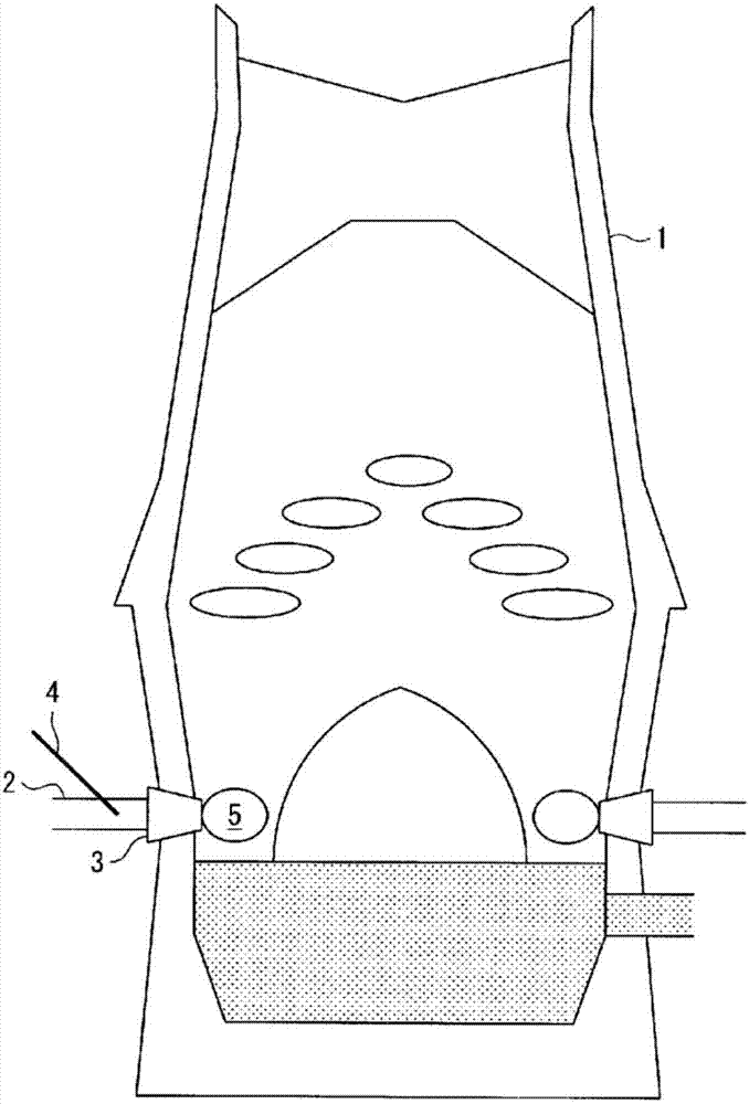
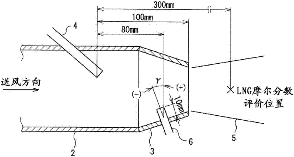
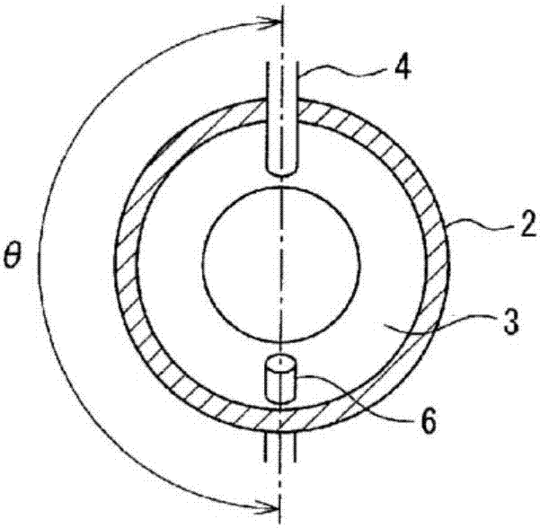
[0024] Next, one embodiment of the blast furnace operating method of the present invention will be described with reference to the drawings. figure 1 It is an overall view of a blast furnace to which the blast furnace operating method of this embodiment is applied. As shown in the figure, an air blowing pipe 2 for sending hot air is connected to a tuyere 3 of a blast furnace 1, and a spray gun 4 is installed so as to pass through the air blowing pipe 2 . Hot air uses air. In the coke accumulation layer in front of the tuyere 3 in the direction of hot air conveyance, there is a combustion space called the swirl zone 5, and in this combustion space, iron ore is mainly reduced, that is, pig iron is produced. In the figure, only one spray gun 4 is inserted into the air supply pipe 2 on the left side of the drawing, but it is well known that the set spray gun can be inserted in any of the air supply pipe 2 and the tuyere 3 arranged in a circumferential shape along the furnace wall...


PUM

PropertyMeasurementUnit
densityaaaaaaaaaa

Abstract

Provided is a method for operating a blast furnace with which the combustion efficiency of a solid fuel such as powdered coal is improved, thereby making it possible to improve productivity and reduce CO2 emissions. Powdered coal and oxygen are blown in from an upstream lance 4 configured from a double tube, and LNG is blown in from a downstream lance 6 located downstream from the upstream lance 4 in the direction of the hot air blast, whereby supplemental oxygen for use in combustion of the LNG is provided from the upstream lance 4, and the powdered coal heated by the combustion of the LNG is combusted together with the supplied oxygen or with oxygen in the air blast. The direction in which the LNG is blown from the downstream lance 6 with respect to the blast direction ranges from -30 to 45degrees, and the position at which the LNG is blown in from the downstream lance 6 with reference to the position at which the upstream lance 4 is inserted into a blast tube 2 ranges from 160 to 200degree expressed in terms of angle in the blast-tube circumferential direction, where a direction perpendicular to the hot air blast direction is designated as 0degree, the downstream direction therefrom in the direction of the hot air blast is designated as positive, and the upstream direction is designated as negative.

Description

technical field [0001] The present invention relates to a method for raising the combustion temperature by blowing pulverized coal from the tuyere of a blast furnace to improve productivity and discharge CO 2 The method of operation of the reduced blast furnace. Background technique [0002] In recent years, global warming due to the increase in the emission of carbon dioxide gas has become a problem. In the iron and steel industry, the emission of CO 2 Inhibition is also an important issue. Affected by this, in recent blast furnace operations, a low reduction agent ratio (low RAR: the abbreviation of Reduction Agent Ratio, the total amount of the reduction agent blown in from the tuyeres and the coke charged from the top of the furnace per 1 ton of pig iron produced )operate. Blast furnaces mainly use coke loaded from the top of the furnace and pulverized coal blown in from the tuyeres as reducing materials. In order to achieve a low ratio of reducing materials and furth...

Claims


Application Information

Patent Timeline
Patent Type & Authority Applications(China)
IPC IPC(8): C21B5/00C21B7/00
CPCC21B5/00C21B5/001C21B5/003C21B7/16C21B7/163C21B2005/005C21B7/00F27B1/16F27D7/02F27D17/00Y02P10/25C21B9/10
Inventor 村尾明纪山本尚贵川岛知之大山伸幸
Owner JFE STEEL CORP
Features
  • Generate Ideas
  • Intellectual Property
  • Life Sciences
  • Materials
  • Tech Scout
  • Unparalleled Data Quality
  • Higher Quality Content
  • 60% Fewer Hallucinations
Learn More