Flue gas denitrification modularized control device

A modular control and denitration technology, applied in electrical program control, program control in sequence/logic controllers, gas treatment, etc., can solve the problems of low electric shock protection level, waste of resources, long installation period, etc. Low level of electric shock protection, reduced waste of cable resources, scientific and reasonable structural design

Inactive Publication Date: 2017-12-01
洛阳格林环保工程有限公司
View PDF0 Cites 0 Cited by
  • Summary
  • Abstract
  • Description
  • Claims
  • Application Information

AI Technical Summary

Problems solved by technology

[0004] The traditional centralized control method in the prior art has the following problems: 1. The level of electric shock protection is not high: because the distance between the equipment and the control cabinet is too far, the protection level of the protective electrical appliances is greatly reduced; 2. The explosion-proof level cannot be guaranteed: because ammonia water belongs to It is volatile and produces explosive gas, and it is very easy to form an explosion hazard area around the ammonia tank. Due to the distance from the power distribution room, if the protective performance of the protective electrical equipment is reduced, sparks are generated due to poor contact during the production process, which is prone to explosion hazards; 3. Resources Waste: For example, if a 5.5KW motor is used on site, if micro-break short circuit and ground fault protection are used, the cable should be 4×2.5mm 2 , the safe use distance is no more than 91 meters. In the traditional centralized mode, the distance between the mixed distribution power supply and the power distribution cabinet is generally greater than 100 meters. In this way, when a fault occurs, the circuit breaker cannot play a protective role.
If you want t

Method used


Image

  • Flue gas denitrification modularized control device
  • Flue gas denitrification modularized control device

Examples


Embodiment Construction

[0024] The specific implementation manners of the present invention will be further described in detail below in conjunction with the accompanying drawings.

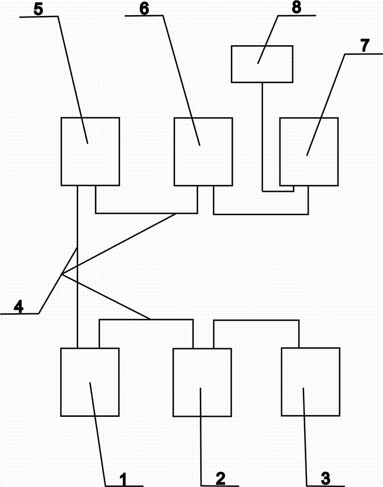
[0025] As shown in the figure, a flue gas denitrification modular control device includes an ammonia water filling and storage unit 1, an ammonia water delivery unit 2, a soft water delivery unit 3, and an open field standard bus 4; the ammonia water filling and storage unit 1 is set in At the bottom left position, from left to right, there are ammonia water delivery unit 2 and soft water delivery unit 3 respectively, ammonia water filling and storage unit 1, ammonia water delivery unit 2 and soft water delivery unit 3 are connected by open field standard bus 4 ; At the left side of the top, there are left mixed distribution unit 5 and right mixed distribution unit 6, and a control management unit 7 is arranged on the right side of the left mixed distribution unit 5 and the right mixed distribution unit 6, and on the left...


PUM


Abstract

The invention discloses a flue gas denitrification modular control device, which includes an ammonia water filling and storage unit, an ammonia water delivery unit, a soft water delivery unit, and an open field standard bus; the ammonia water filling and storage unit is arranged at the bottom left position, From left to right, there are ammonia water delivery unit, soft water delivery unit, ammonia water filling and storage unit, ammonia water delivery unit and soft water delivery unit are connected by open field standard bus; there is a left mixing distribution unit on the upper left side 1. The right hybrid distribution unit, a control management unit is arranged on the right side of the left hybrid distribution unit and the right hybrid distribution unit, and a collection and distribution control unit is arranged on the upper left side of the control management unit. This modular control device for flue gas denitrification greatly enhances the safety performance of the modular control system, reduces the waste of cable resources, shortens the installation and commissioning period, and prolongs the service life of equipment and meters.

Description

technical field [0001] The invention belongs to the technical field of desulfurization and denitrification flue gas denitrification selective non-catalytic reduction system, and in particular relates to a flue gas denitrification modular control device. Background technique [0002] Selective non-catalytic reduction (SNCR) refers to the reduction of nitrogen oxides in the flue gas to harmless nitrogen and water by spraying a reducing agent in the "temperature window" suitable for denitrification reaction without the action of a catalyst. Generally, ammonia, urea or hydrogen acid in the furnace is used as the reducing agent to reduce NOx. The reducing agent only reacts with NOx in the flue gas, and generally does not react with oxygen. This technology does not use a catalyst, so this method is called a selective non-catalytic reduction method; since this process does not use a catalyst, it must be added in the high temperature area. agent (ammonia). [0003] The electrical ...

Claims


Application Information

Patent Timeline
IPC IPC(8): B01D53/56B01D53/79G05B19/04
CPCB01D53/56B01D53/79B01D2251/2062B01D2258/0283G05B19/04
Inventor 郭召军马红云
Owner 洛阳格林环保工程有限公司
Why Eureka
Try Eureka