
Vibration type flotation tank

A flotation tank, vibrating technology, used in flotation water/sewage treatment, water/sewage treatment, flocculation/sedimentation water/sewage treatment, etc., can solve the problems of floc decomposition, affecting filtration steps, uneven reaction, etc. To achieve the effect of slow stirring speed, speeding up dispersing speed and increasing dispersing motion

Active Publication Date: 2017-12-01
JIAXING QIUWEITE KNITTING GARMENTS
View PDF11 Cites 3 Cited by
  • Summary
  • Abstract
  • Description
  • Claims
  • Application Information

AI Technical Summary

Problems solved by technology

[0004] Although the development of air flotation and dissolved air equipment and slag scraping machine is very mature, there are still some minor problems in the whole air flotation step, such as during the dosing reaction, because the water flow is in a flowing state during the whole process of the air flotation step, Therefore, there are generally insufficient stirring, uneven reaction, or too violent stirring that leads to the decomposition of flocs. The scum left is still mixed in the clear water, and the removal of scum is not complete, which will affect the subsequent filtration steps. If there is too much scum, it will penetrate the filter layer and make the filter layer lose its filtering effect. Therefore, it is urgent to invent an air flotation tank to solve the above problems. question

Method used


Image

  • Vibration type flotation tank

Examples


Embodiment Construction

[0033] The present invention will be further described in detail below in conjunction with the accompanying drawings, so that those skilled in the art can implement it with reference to the description.

[0034] In the description of the present invention, the orientations or positional relationships indicated by the terms "transverse", "upper", "lower", "top", "bottom", "inner", "outer" etc. are based on the orientations shown in the drawings Or positional relationship is only for the convenience of describing the present invention and simplifying the description, and does not indicate or imply that the referred device or element must have a specific orientation, be constructed and operated in a specific orientation, and therefore should not be construed as a limitation of the present invention.

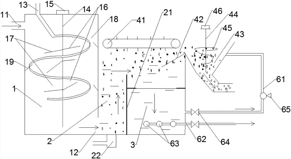
[0035] Such as figure 1 As shown, the present invention provides a vibrating air flotation tank, comprising:

[0036]Reaction tank 1, its upper end is provided with raw water inlet...


PUM

PropertyMeasurementUnit
widthaaaaaaaaaa
lengthaaaaaaaaaa
widthaaaaaaaaaa

Abstract

The invention discloses a vibration flotation tank, which comprises a reaction tank and a contact and separation tank, wherein the upper end of the reaction tank is provided with a raw water inlet, the lower end is provided with a raw water outlet and the top is provided with a medicine inlet; a first stirring device is arranged in the reaction tank, and a controller controls a first motor to drive a first stirring shaft to rotate forwardly by two revolutions and then rotate reversely by two revolutions to do periodically progressive rotation movement; the contact and separation tank is located downstream of the reaction tank and is internally provided with a vertical partition plate, and the partition plate is used for separating the contact and separation tank into an upstream contact zone and a downstream separation zone; the separation zone comprises a dross removing assembly, a vibration assembly, a vibration assembly and a water outlet assembly; the vibration assembly is disposed in the separation zone, is lower than the upper end of the partition plate, and comprises a vibration screen; the controller controls the vibration frequency and amplitude of the vibration screen; the water outlet assembly is disposed below the vibration assembly. The vibration type flotation tank of the invention has the advantages of enabling the dosing reaction to be more uniform in an air flotation step, reducing destruction on stability of flocs, and realizing more thorough dross removal and more convenient dross transfer.

Description

technical field [0001] The invention relates to the field of sewage treatment. More specifically, the present invention relates to a vibrating air flotation tank. Background technique [0002] Sewage treatment technology mainly includes the following steps, pretreatment, coagulation and sedimentation, flotation and air flotation, filtration, redox, activated carbon adsorption, and membrane separation. Among them, flotation is mainly treated by natural flotation devices to separate substances with a specific gravity lower than water, such as oil. , and the substance with a specific gravity greater than water is processed by an air flotation device. The principle is that the fine air bubbles first adhere to the suspended particles in the water to form a "bubble-particle" complex with an overall density lower than that of water, so that the suspended particles float together with the air bubbles. Raise to the surface of the water, and then scrape off the scum with a scum scrap...

Claims


Application Information

Patent Timeline
Patent Type & Authority Applications(China)
IPC IPC(8): C02F1/24C02F1/52
CPCC02F1/24C02F1/52C02F2201/002
Inventor 韦爱龄
Owner JIAXING QIUWEITE KNITTING GARMENTS
Learn More