Full-automatic numerical control hydraulic turnout tamping wagon

A fully automatic, tamping vehicle technology, applied in the direction of roads, tracks, ballast layers, etc., can solve the problems of manual cooperation, equipment damage, low operation efficiency of portable small road maintenance equipment, etc., and achieve the effect of meeting the operation requirements.

Active Publication Date: 2017-12-01
淄博洁翔机电科技开发有限公司
View PDF11 Cites 4 Cited by
  • Summary
  • Abstract
  • Description
  • Claims
  • Application Information

AI Technical Summary

Problems solved by technology

Although large-scale road maintenance machinery has a high degree of automation and the ability to realize comprehensive operations, large-scale road maintenance machinery is expensive and expensive to use, it is difficult to popularize and use, and it has the disadvantage of requiring manual cooperation during the operation process
The turnouts are distributed at both ends of the station and the station yard. This layout makes the large-scale road maintenance machinery unable to work continuously, and the utilization rate of the expensive large-scale road maintenance machinery is not high.
Although the design of large road maintenance machinery can realize all the tamping operations on the curved strand rails of the turnout, the tamping of the far end of the long turnout sleeper is easy to cause damage to the equipment, and only most of the tamping operations of the turnout are completed in the actual operation process The far end of some long fork sleepers still nee

Method used


Image

  • Full-automatic numerical control hydraulic turnout tamping wagon
  • Full-automatic numerical control hydraulic turnout tamping wagon
  • Full-automatic numerical control hydraulic turnout tamping wagon

Examples


Embodiment Construction

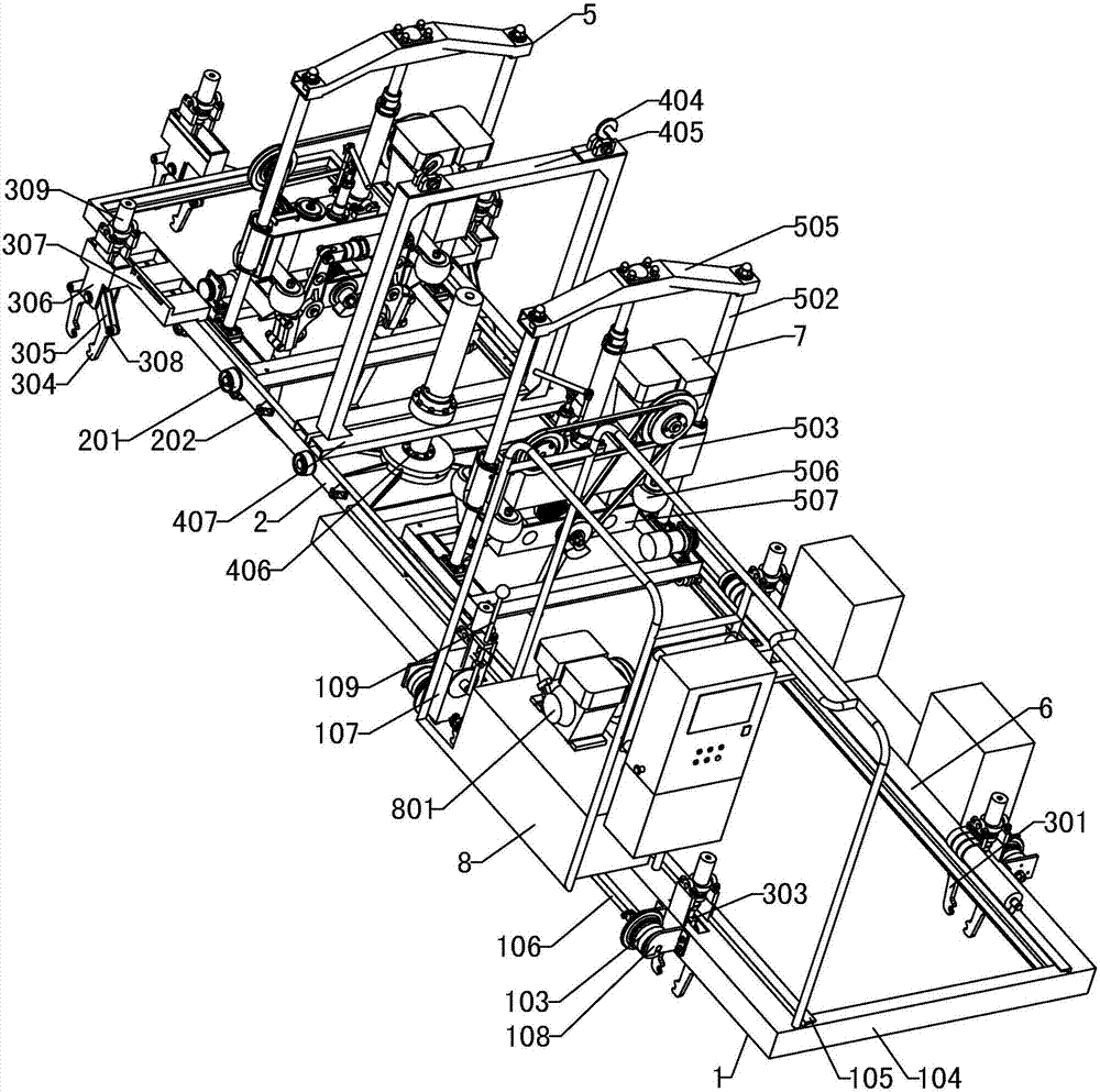
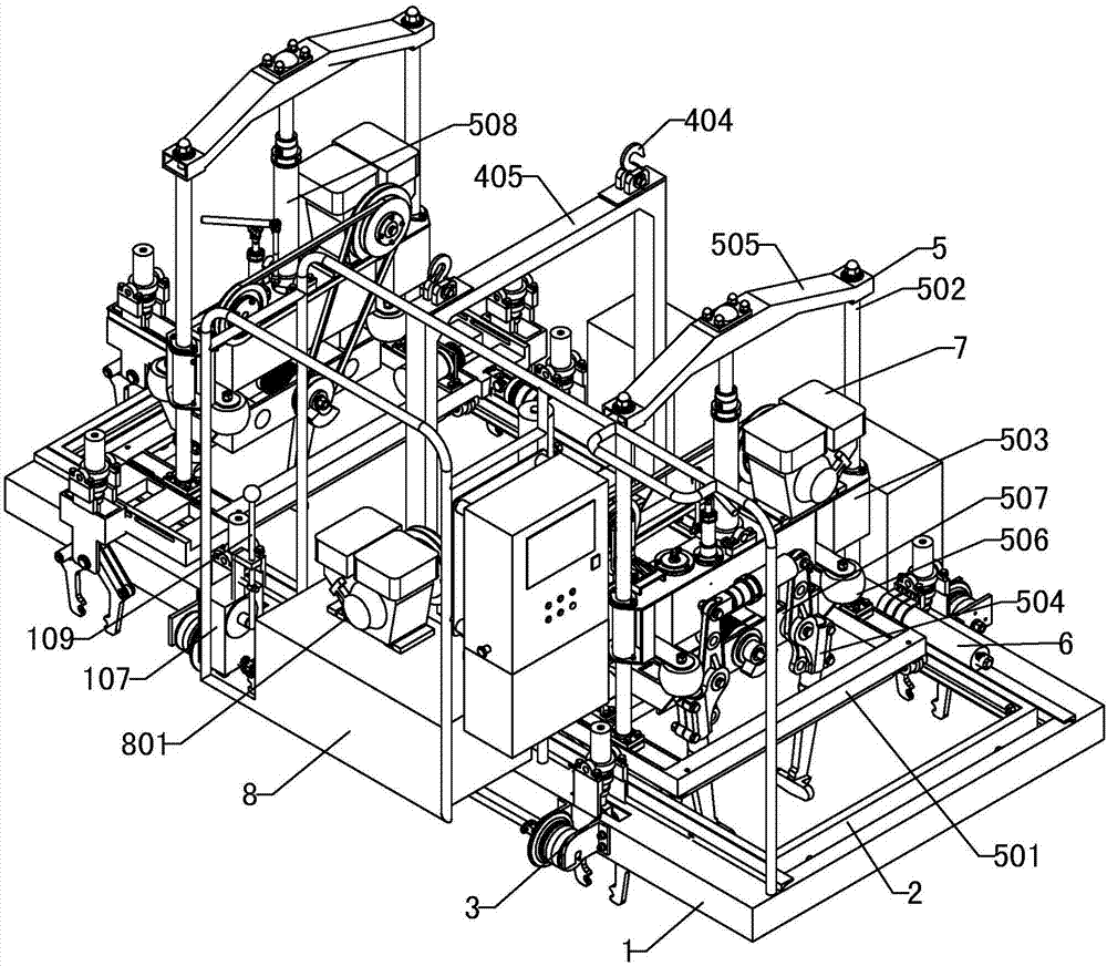
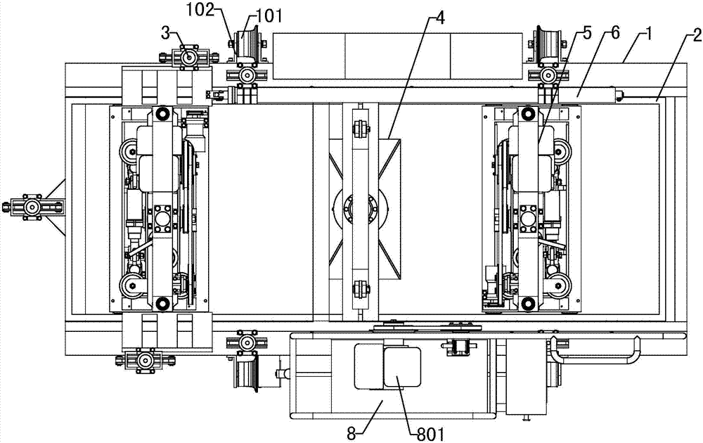
[0040] Figure 1~5 It is the best embodiment of the present invention, below in conjunction with attached Figure 1~5 The present invention will be further described.

[0041] Refer to attached Figure 1~5 : Fully automatic CNC hydraulic turnout tamping vehicle, including a tamping mechanism 5, a self-propelled chassis is installed at the bottom of the tamping mechanism 5, the chassis includes a bottom walking chassis 1 and a mobile chassis 2, and the walking chassis 1 is front and rear along the railway line traveling direction The traveling mechanism is set, and the mobile chassis 2 is connected to the traveling chassis 1 in a horizontal and telescopic manner. The tamping mechanism 5 is provided with two groups. There is a rail clamping mechanism 3 for clamping the rail, and the middle part of the mobile chassis 2 is provided with a lower mechanism 4 that drives the whole machine up and down and can rotate; one side of the walking chassis 1 and a tamping mechanism 5 are re...


PUM


Abstract

The invention provides a full-automatic numerical control hydraulic turnout tamping wagon, and belongs to the field of railway sleeper underneath turnout tamping equipment. The full-automatic numerical control hydraulic turnout tamping wagon is characterized in that a chassis comprises a travelling chassis (1) and a moving chassis (2), wherein the moving chassis (2) is connected with the travelling chassis (1) in a traverse telescoping mode. Two tamping mechanisms (5) are installed on the moving chassis (2) in a transverse movement mode. Rail clamping mechanisms (3) which are used for clamping steel rails are arranged on the travelling chassis (1) and the moving chassis (2). A railway leaving mechanism (4) is arranged in the middle of the moving chassis (2). A locating sensor which detects the travelling operation position of a complete machine is arranged on the travelling chassis (1), and a detection sensor which detects the return position and a locating sensor which detects the position of a clamped rail are arranged on the moving chassis (2). By the adoption of the full-automatic numerical control hydraulic turnout tamping wagon, all operation such as equipment transfer, automatic tamping operation of all turnouts and railway coming and leaving operation of equipment can be achieved by a single worker, manpower is saved, the working quality is improved, the interference on train travelling is low, and the industrial upgrade of the railway line turnout tamping operation from mechanization to automation is achieved.

Description

technical field [0001] The utility model relates to a fully automatic numerically controlled hydraulic turnout tamping vehicle, which belongs to the field of tamping equipment for railway under-pillow turnouts. Background technique [0002] The ballasted ballast bed of the railway will deform and sink due to the rolling effect of the running vehicles. In order to restore the smoothness of the line to ensure the safe and high-speed operation of the train, regular turnout tamping operations are required. Therefore, turnout tamping operations are an important task for railway line maintenance operations. [0003] The ballast tamping operation under the railway line turnout pillow has always been a difficult task. The existing various types of small turnout tamping machines are cumbersome to use, and some models are easy to fall off during use. It is necessary to move the whole machine, and the heavy traveling frame is difficult to evacuate the railway line only by the operator...

Claims


Application Information

Patent Timeline
IPC IPC(8): E01B27/20
CPCE01B27/20E01B2203/125
Inventor 孟繁洁孟庆梁张忠亮
Owner 淄博洁翔机电科技开发有限公司
Why Eureka
Try Eureka