Amplifying circuit for high-frequency signal common mode rejection based on current feedback operational amplifier

A current feedback and amplifying circuit technology, applied in the direction of DC-coupled DC amplifiers, amplifiers with semiconductor devices/discharge tubes, amplifiers, etc. Mode gain and other issues to achieve high-precision discrimination, high-bandwidth characteristics, and suppression of common-mode signals and noise

Pending Publication Date: 2017-12-01
ZHEJIANG QUANTUM TECH CO LTD
View PDF0 Cites 1 Cited by
  • Summary
  • Abstract
  • Description
  • Claims
  • Application Information

AI Technical Summary

Problems solved by technology

However, in the radio frequency field, the method of first subtracting the power and then amplifying the RF, the frequency characteristics of the gain are greatly affected by the discrete parameters, and cannot meet the requirements of common-mode suppression. Limitation of dynamic range, can not meet the requirements of high differential mode gain

Method used


Image

  • Amplifying circuit for high-frequency signal common mode rejection based on current feedback operational amplifier
  • Amplifying circuit for high-frequency signal common mode rejection based on current feedback operational amplifier
  • Amplifying circuit for high-frequency signal common mode rejection based on current feedback operational amplifier

Examples


Embodiment Construction

[0013] The present invention will be clearly and completely described below with reference to the accompanying drawings in the embodiments of the present invention.

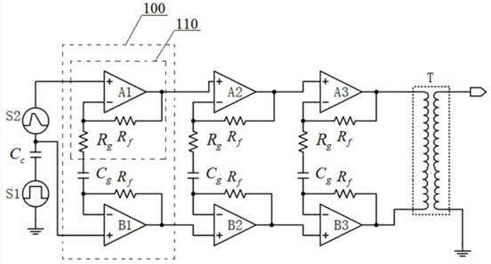
[0014] Such as figure 1 As shown, an amplifying circuit based on a current feedback operational amplifier to realize common-mode rejection of high-frequency signals is composed of n-stage instrument amplifier circuits 100 cascaded, wherein, n≥1, and the instrument amplifier circuits 100 of each stage are It is composed of two current feedback operational amplifiers 110 connected in parallel, the inverting input terminal and output terminal of the current feedback operational amplifier 110 are connected with a feedback resistor Rf, and the two current feedback operational amplifiers of the instrument amplifier circuit 100 of the same stage The inverting input ends of 110 are all connected through the gain resistor Rg and the capacitor Cg, and the first-stage instrumentation amplifier circuit includes a current fee...


PUM


Abstract

An amplifying circuit based on a current feedback operational amplifier to realize common-mode rejection of high-frequency signals, which is composed of cascaded n-level instrumentation amplifier circuits, wherein, n≥1, and the instrumentation amplifier circuits of each level are composed of two current-feedback The non-inverting input terminal of the current feedback operational amplifier B1 is connected to the spike signal source, and the same input terminal of the current feedback operational amplifier A1 is connected to the avalanche signal source (the avalanche signal will be superimposed on the spike signal), and the current The output terminal of the feedback operational amplifier An and the output terminal of the current feedback operational amplifier Bn are respectively connected to two input terminals of a radio frequency transformer T. The present invention solves the technical defect that high differential mode gain cannot be achieved by using radio frequency amplifiers, and has the characteristics of high common mode rejection ratio; its high bandwidth characteristics meet the requirements of high frequency signal processing, and at the same time, the method of cascaded gain solves the problem caused by The problem of limited gain of the current feedback method also achieves the purpose of realizing high-precision identification of avalanche signals.

Description

technical field [0001] The invention relates to the technical field of high-speed analog signal conditioning circuits for single-photon detectors, in particular to an amplifying circuit based on a current feedback operational amplifier to realize common-mode suppression of high-frequency signals. Background technique [0002] In quantum key distribution (QKD), parameters such as dark count rate, post-pulse count rate, and dead time of single photon detectors based on avalanche diodes are limited by the performance of the avalanche signal conditioning circuit. Because in the gating mode, the gating signal is capacitively coupled into the signal path through the avalanche diode junction, thus generating a spike whose amplitude is several tens of times that of the avalanche signal; while the avalanche signal conditioning circuit amplifies the avalanche signal, it needs to Spike pulses are suppressed to ensure that the back-end circuit can discriminate small enough avalanche sig...

Claims


Application Information

Patent Timeline
Patent Type & Authority Applications(China)
IPC IPC(8): H03F3/45
CPCH03F3/45479
Inventor 周朝阳曹文钊赵义博
Owner ZHEJIANG QUANTUM TECH CO LTD
Why Eureka
Try Eureka